High efficiency optical devices

a high-efficiency, optical device technology, applied in the direction of instruments, polarising elements, planar/plate-like light guides, etc., can solve the problems of large overall output of the optical device, large bulky and/or heavy conventional reflectors, and low film absorption. , to achieve the effect of low film absorption

Inactive Publication Date: 2005-08-02
3M INNOVATIVE PROPERTIES CO
View PDF155 Cites 85 Cited by
  • Summary
  • Abstract
  • Description
  • Claims
  • Application Information

AI Technical Summary

Benefits of technology

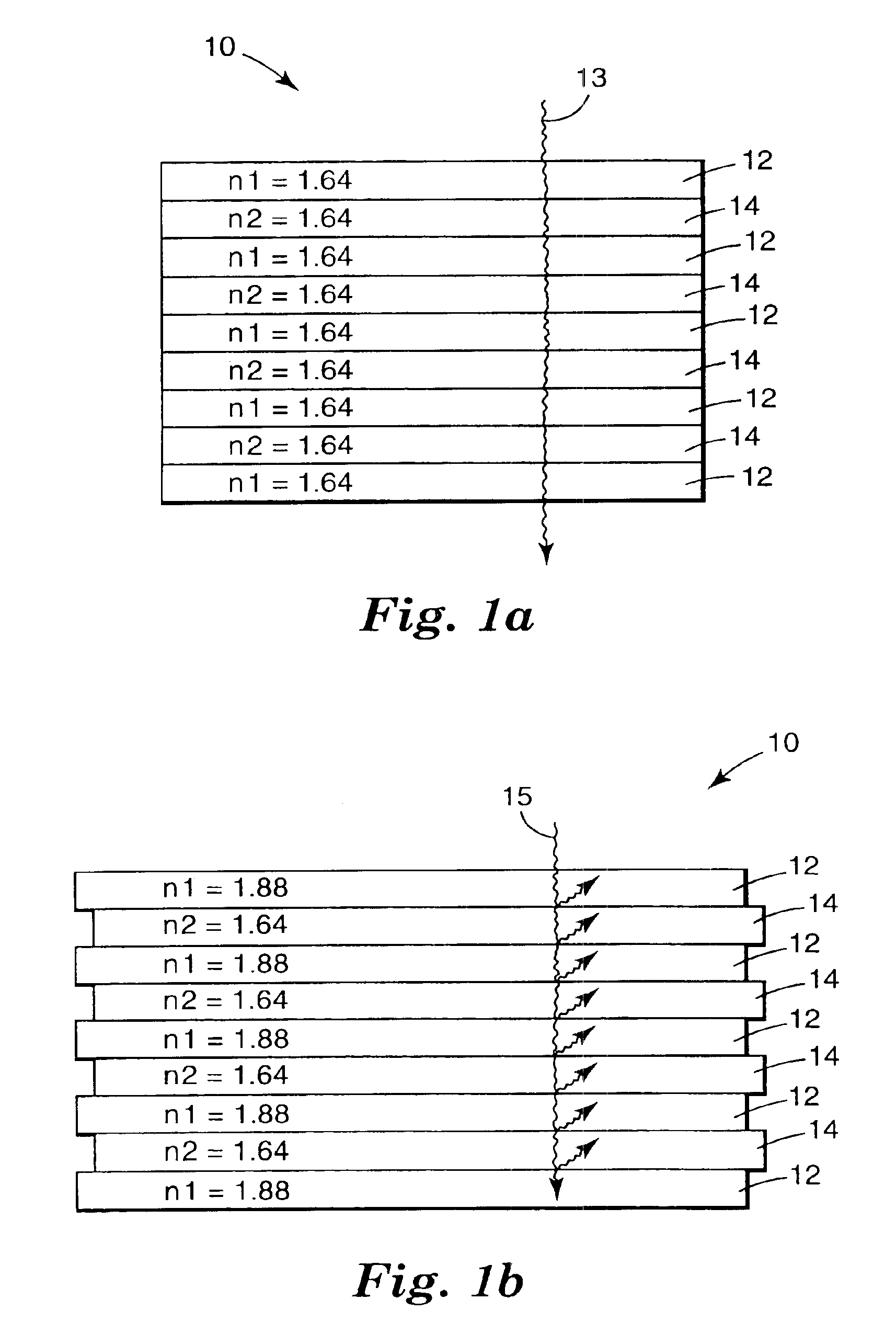
[0013]Optical devices according to the present invention include a multilayer optical film. Optical devices incorporating multilayer optical film according to the present invention enjoy many advantages due to the low absorptivity of the film and its ability to reflect light approaching at shallow angles as well as normal to the film.
[0014]In those situations where complete reflectivity is desired, optical devices employing a multilayer optical film according to the present invention can reflect over 99% of the light striking the surface of the film.
[0015]If a reflective polarizer is desired, the optical devices can be constructed with a multilayer optical film which transmits a significant amount of light having one plane of polarization while reflecting a significant amount of light having an orthogonally oriented polarization. A further advantage is that the relative percentages of transmitted / reflected light can be largely controlled by the multilayer optical film used in the present invention.

Problems solved by technology

The conventional reflectors suffer from relatively high absorbance of light incident on their surfaces, typically absorbing about 4-10% of the light incident on them.
In devices in which multiple reflections are encountered, the overall output of the optical device can be substantially limited.
In addition, many of the conventional reflectors are too bulky and / or heavy for many of the applications, particularly in laptop computer displays and other portable devices.
Absorptive polarizers do, of course, contribute to the absorptive losses of optical devices in which they are used, thereby limiting the output of those devices.
To overcome the problems associated with absorptive losses, many signs typically employ numerous light sources, thereby increasing the cost to manufacture and operate the signs.
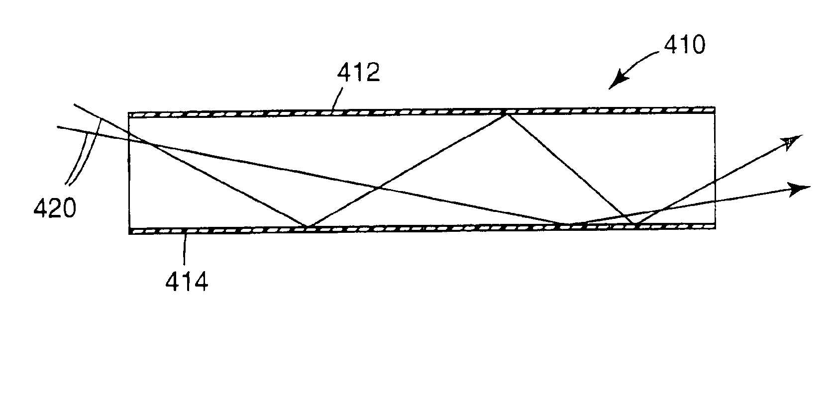
Each reflection results in some absorption when conventional reflectors are used, thereby limiting throughput of the light pipe.
Such polymeric films are, however, subject to a number of other disadvantages including iridescence, as well as poor reflectivity when off-axis light approaches the surface of the film.
The off-axis light is typically transmitted through the films, rather than being reflected, thereby resulting in transmissive losses rather than absorptive losses.
Whether light is lost through absorption or transmission, however, the output of the optical device is limited.
Other problems with known multi-layer polymer films used to provide reflectors and / or polarizers is that the materials and methods used to manufacture the films presents serious problems due to poor optical transmission, extrudibility, and high costs.

Method used


Image

  • High efficiency optical devices
  • High efficiency optical devices
  • High efficiency optical devices

Examples


example 1

PEN:THV 500, 449, Mirror

[0068]A coextruded film containing 449 layers was made by extruding the cast web in one operation and later orienting the film in a laboratory film-stretching apparatus. A Polyethylene naphthalate (PEN), with an Intrinsic Viscosity of 0.53 dl / g (60 wt. % phenol / 40 wt. % dichlorobenzene) was delivered by one extruder at a rate of 56 pounds per hour and THV 500 (a fluoropolymer available from Minnesota Mining and Manufacturing Company) was delivered by another extruder at a rate of 11 pounds per hour. The PEN was on the skin layers and 50% of the PEN was present in the two skin layers. The feedblock method was used to generate 57 layers which was passed through three multipliers producing an extrudate of 449 layers. The cast web was 20 mils thick and 12 inches wide. The web was later biaxially oriented using a laboratory stretching device that uses a pantograph to grip a square section of film and simultaneously stretch it in both directions at a uniform rate. ...

example 2

PEN:PMMA, 601, Mirror

[0070]A coextruded film containing 601 layers was made on a sequential flat-film-making line via a coextrusion process. Polyethylene Naphthalate (PEN) with an Intrinsic Viscosity of 0.57 dl / g (60 wt. % phenol / 40 wt. % dichlorobenzene) was delivered by extruder A at a rate of 114 pounds per hour with 64 pounds per hour going to the feedblock and the rest going to skin layers described below. PMMA (CP-82 from ICI of Americas) was delivered by extruder B at a rate of 61 pounds per hour with all of it going to the feedblock. PEN was on the skin layers of the feedblock. The feedblock method was used to generate 151 layers using the feedblock such as those described in U.S. Pat. No. 3,801,429, after the feedblock two symmetric skin layers were coextruded using extruder C metering about 30 pounds per hour of the same type of PEN delivered by extruder A. This extrudate passed through two multipliers producing an extrudate of about 601 layers. U.S. Pat. No. 3,565,985 des...

example 3

PEN:PCTG, 449, Polarizer

[0072]A coextruded film containing 481 layers was made by extruding the cast web in one operation and later orienting the film in a laboratory film-stretching apparatus. The feedblock method was used with a 61 layer feedblock and three (2×) multipliers. Thick skin layers were added between the final multiplier and the die. Polyethylene naphthalate (PEN) with an intrinsic viscosity of 0.47 dl / g (60 wt. % phenol / 40 wt. % dichlorobenzene) was delivered to the feedblock by one extruder at a rate of 25.0 pounds per hour. Glycol modified polyethylene dimethyl cyclohexane terephthalate (PCTG 5445 from Eastman) was delivered by another extruder at a rate of 25.0 pounds per hour. Another stream of PEN from the above extruder was added as skin layers after the multipliers at a rate of 25.0 pounds per hour. The cast web was 0.007 inches thick and 12 inches wide. The web was layer uniaxially oriented using a laboratory stretching device that uses a pantograph to grip a s...


PUM

PropertyMeasurementUnit
reflectivityaaaaaaaaaa
thicknessaaaaaaaaaa
reflectanceaaaaaaaaaa

Abstract

Optical devices according to the present invention include a multilayer optical film in which at least one of the layers comprises an oriented birefringent polymer. The multilayer optical film exhibits low absorptivity and can reflect light approaching at shallow angles as well as normal to the film.

Description

CROSS REFERENCE TO RELATED APPLICATIONS[0001]This application is a continuation of U.S. application Ser. No. 09 / 777,455, filed Feb. 6, 2001 and issued as U.S. Pat. No. 6,641,883, which is a divisional of U.S. application Ser. No. 09 / 461,245, filed Dec. 15, 1999 and issued as U.S. Pat. No. 6,210,785, which is a continuation of U.S. application Ser. No. 08 / 494,366, filed Jun. 26, 1995 and issued as U.S. Pat. No. 6,080,467.FIELD OF THE INVENTION[0002]The present invention relates to the field of optical devices. More particularly, the present invention relates to optical devices employing multi-layer optical film as reflectors and / or polarizers.BACKGROUND OF THE INVENTION[0003]Optical devices employing reflectors are used, for example, in displays for laptop computers, hand-held calculators, digital watches and similar devices as well as illuminated signs, light pipes, backlight assemblies and many other devices.[0004]Conventional reflectors, including pigmented surfaces, silvered mirr...

Claims


Application Information

Patent Timeline
Patent Type & Authority Patents(United States)
IPC IPC(8): G02B1/10G02B5/30G02B5/08B32B3/10B32B7/023B32B27/36F21V8/00G02B5/26G02B5/28G02F1/1335G02F1/13357
CPCB32B7/02B32B27/30B32B27/302B32B27/304B32B27/322B32B27/36G02B5/0841G02B5/305G02B5/3083G02B6/005G02B6/0055G02B6/0056G02B6/0096G02F1/13362B32B27/08Y10T428/24942B32B2250/05B32B2250/42B32B2307/42B32B2307/518B32B2307/704B32B2457/20B32B2551/00G02B6/0046G02F1/133615G02F2001/133545Y10S428/91Y10T428/1393Y10T428/1352Y10T428/13Y10T428/24967Y10T428/24322Y10T428/139Y10T428/31935Y10T428/31938Y10T428/31786Y10T428/31797Y10T428/31504G02F1/133545B32B7/023
Inventor OUDERKIRK, ANDREW J.WEBER, MICHAEL F.COBB, JR., SANFORDWORTMAN, DAVID L.
Owner 3M INNOVATIVE PROPERTIES CO
Why Eureka
Try Eureka