Remote image management system (RIMS)

a technology of image management system and remote image, applied in the field of object detection, recognition and location systems, can solve the problems of increased sensitivity at the cost of increased size and weight, and high operating cos

Inactive Publication Date: 2005-08-02
LAHN RICHARD H
View PDF3 Cites 27 Cited by
  • Summary
  • Abstract
  • Description
  • Claims
  • Application Information

AI Technical Summary

Benefits of technology

[0019]The Remote Image Management System (RIMS) described herein eliminates the need for manned aircraft, airborne personnel, and their expensive support systems. One of its key attributes is that it is small and simple enough to permit the use of a Mini Unmanned Air Vehicle (MUAV) weighing less than 4.5 kilograms.
[0021]The ground based element is an operator's GCU including radio transmitters and receivers comprisng a communication link between the GCU and the air vehicle, an image processing unit, comprised of a single or multiple CPUs and a display and control interface with the operator. In operation, the sensor LOS is directed to an area of interest by either automatic control of the FMS or by the ground operator. Its imagery is down linked to the GCU along with data containing the air vehicle location and sensor pointing angle. The GCU data link receives the imagery and data and routes it to the image management system. The image management system processes the imagery to eliminate the clutter of false targets by performing detection, identification, recognition and moving target detection algorithms. The purpose for performing these algorithms is to identify potential objects of interest by eliminating non targets. These objects of interest are highlighted and displayed to the operator thus reducing the operator workload and enabling him to concentrate only on potential targets. This reduction of workload permits the operator to find targets in real or near real time more readily than if he were forced to review the entire scene unaided and eliminate the clutter objects himself.

Problems solved by technology

Sensitivity limitations ultimately affect the quality and the detail of the images which may be obtained.
These approaches trade increased sensitivity at the cost of increased size and weight.
These systems, whether manned or unmanned, require highly trained personnel, are expensive to operate, and at times put the human operators in harms way.
In addition, they require complex logistics systems to service, maintain and support the sensor, the airframe which carries it, and the air crew.
MUAV surveillance systems are however, severely constrained by their own weight, size, and power limitations.
In turn, MUAVs tactical capabilities are limited due to the performance of existing state of the art technology for small, light-weight night vision, infrared (IR) sensors.
The sensor must be uncooled because use of a cryostatic device to cool the sensor would impose unacceptable power and weight requirements.
Today's state of the art uncooled sensors have limited resolution, requiring a narrow field of view (FOV) in the range of 15 degrees or a telephoto lens to resolve ground objects.
In addition, weight and power limitations of an MUAV preclude the use of a three axis, stabilized, gimbaled platform to direct the sensor.
The use of a fixed, narrow FOV sensor imposes several limitations on the system which inhibit its ability to effectively perform its mission.
In either case there is insufficient time in the FOV for operator recognition.
The time required to search even a small area is excessive if the MUAV is forced to fly at speeds slow enough to enable the operator to recognize targets because of the narrow sensor footprint over the ground.
A circular loiter pattern is not feasible with a fixed camera because the bank angle of the aircraft would be greater than 15 degrees.
Use of an on-board laser range finder is not possible because of payload weight constraints of MAUVs.
Significant errors can be introduced in the situation where the terrain is in fact mountainous or hilly.

Method used


Image

  • Remote image management system (RIMS)
  • Remote image management system (RIMS)
  • Remote image management system (RIMS)

Examples


Embodiment Construction

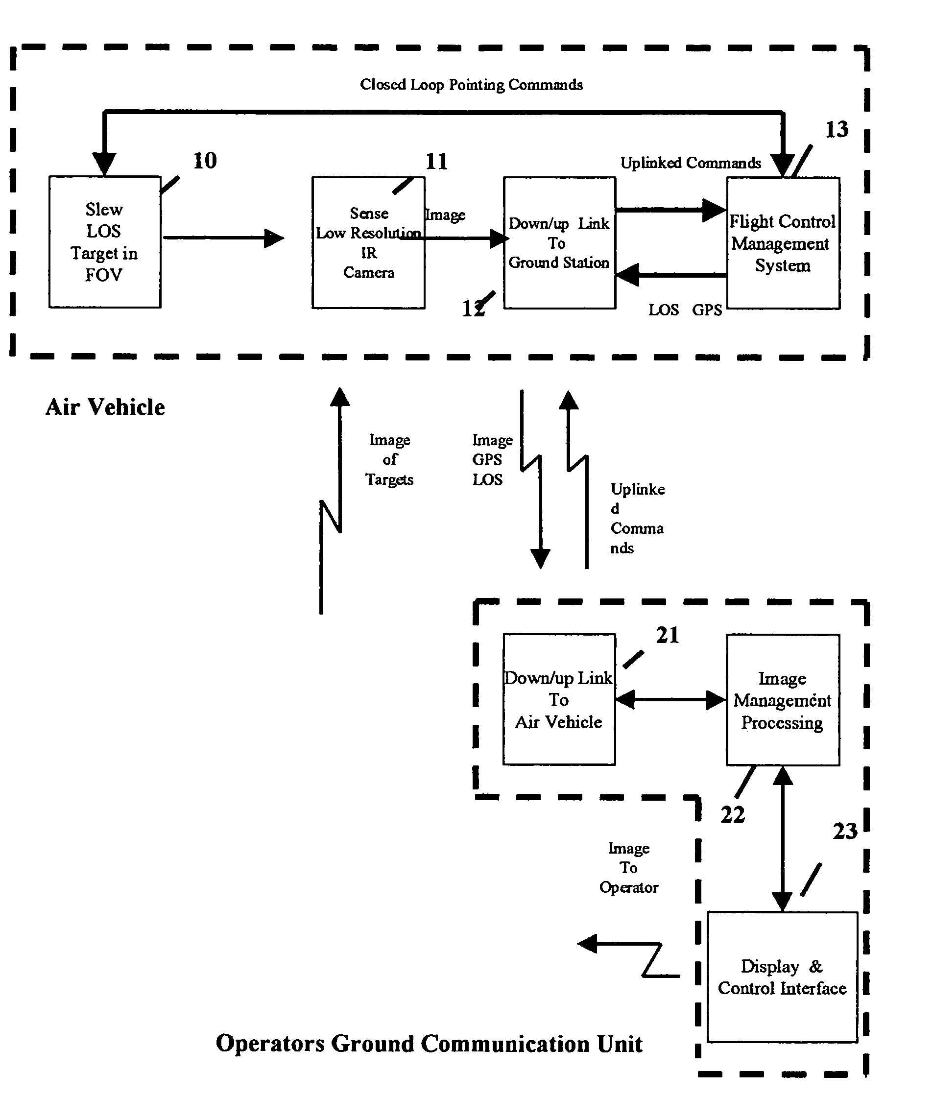
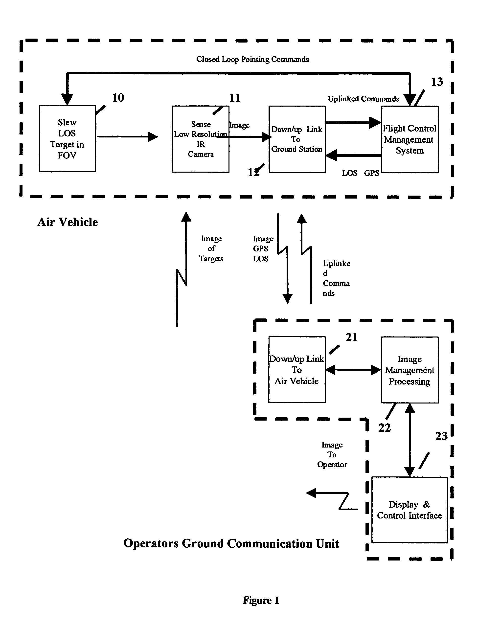
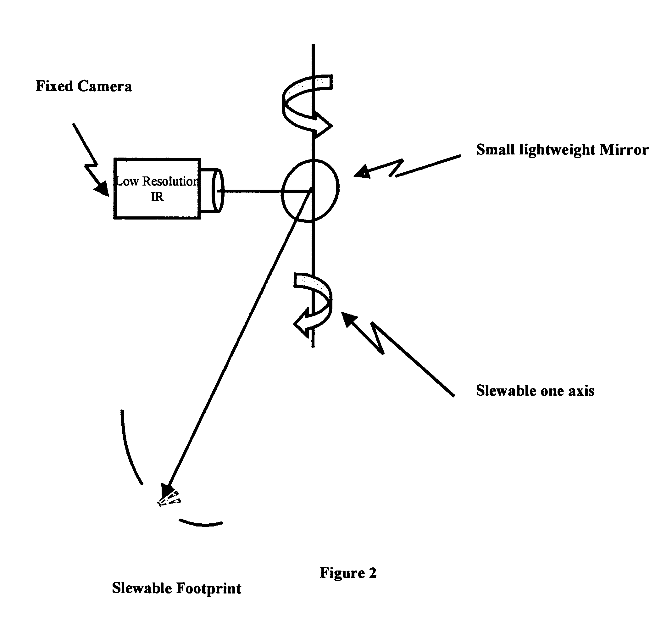
[0027]Referring to FIG. 1, System Block Diagram, LOS slew device, 10 is a lightweight device which enables the Line of Sight of the sensor to be directed to an area of interest. This device may consist of a lightweight mirror rotatable on a single axis or a 3 axis tilt and pan mechanism. The control of the LOS slew device may be either automatic through preprogrammed direction from the FMS 13 or by control of the operator on the ground. LOS slew device is described in more detail in FIG. 2. Slewing of the LOS, can be accomplished using the single axis mirror technique shown in FIG. 2. A 3 axis pan and tilt mechanism may also be employed. A stabilized 3 axis gimbal mechanisms are generally too heavy to be accommodated in a MUAV.

[0028]The LOS sensor 10, will be coupled with the aircraft attitude in pitch, yaw, and roll (which is under control of the Flight Management system) to provide a LOS pointing capability of a three axis gimbal with the cost, power, and weight savings of a singl...


PUM


Abstract

A data processing system is which enables an operator to rapidly perform object detection, identification, recognition, and location using remote imagery from Mini Unmanned Air Vehicles when sensor performance is severely limited due to size, weight, and power constraints. The system receives down linked images from an Unmanned Air Vehicle as well as vehicle geographic position and sensor attitude data. The imagery is processed on the ground using detection, identification, recognition and moving target detection algorithms to eliminate clutter and preselect potential objects of interest. The objects of interest are identified by the operator from the preselected list of objects automatically presented to him. The target location is simultaneously calculated for selected objects using the down linked vehicle location and sensor pointing angle and displayed to the operator.

Description

CROSS REFERENCE TO RELATED APPLICATIONS[0001]This Application claims the benefit of U.S. Provisional Application No. 60 / 240,041, filed Oct. 16, 2000.STATEMENT CONCERNING FEDERALLY SPONSORED RESEARCH OR DEVELOPMENT[0002]Not ApplicableREFERENCE TO A MICROFICHE APPENDIX[0003]Not ApplicableBACKGROUND OF THE INVENTION[0004]1. Field of Invention[0005]The present invention generally relates to object detection, recognition and location systems where sensor performance is severely limited due to size, weight and power constraints.[0006]2. Background of the Invention[0007]Current aerial surveillance and targeting systems are subject to the same fundamental design constraints: 1) Use of IR detection sensors for night-time and all weather capability; 2) some form of gimbaling mechanism to reorient the position of the sensor either to seek out new objects or to maintain the line of sight of the sensor relative to the object of interest while compensating for the forward motion of the airborne p...

Claims


Application Information

Patent Timeline
Patent Type & Authority Patents(United States)
IPC IPC(8): B64C13/00B64C13/20G01C21/00G01C22/00G01S5/00G01S5/16
CPCG01S5/0009G01S5/16
Inventor LAHN, RICHARD H.
Owner LAHN RICHARD H
Why Eureka
Try Eureka