
Method and apparatus for power routing in an integrated circuit

a technology of integrated circuits and power routing, applied in computer aided design, instruments, semiconductor/solid-state device details, etc., can solve problems such as power routing, irregular and unpredictable geometry, and not optimized for performance, and achieve the effect of robust vertical and lateral

Inactive Publication Date: 2005-08-02
SYNAPTICS INC
View PDF8 Cites 157 Cited by
  • Summary
  • Abstract
  • Description
  • Claims
  • Application Information

AI Technical Summary

Problems solved by technology

While standard cells are typically easier and faster for a designer to lay out and interconnect, they may not be optimized for performance.
Macros, while optimized for performance and organized into and treated like other blocks, typically have irregular and unpredictable geometry and signal / power pin locations.
Among the many design challenges facing the SOC integrator is the physical placement and routing of the design, a process referred to as “floorplanning”.
One particularly troublesome aspect of floorplanning is power routing.
Because macros contain signal and power pins in irregular locations, while standard cells possess much more regularity, the routing of power among macros and standard cells is often cumbersome and inefficient.
Inefficient integration of circuit blocks such as standard cells and macros can make the chip prohibitively large and cause unwanted timing and delay side effects.
This approach, however, wastes precious die space that could be used for other purposes or even eliminated.
This technique also typically involves use of an additional power bus between the I / O ring and chip core, a practice that is likewise wasteful and can create uneven power distribution for the chip.

Method used


Image

  • Method and apparatus for power routing in an integrated circuit
  • Method and apparatus for power routing in an integrated circuit
  • Method and apparatus for power routing in an integrated circuit

Examples


Embodiment Construction

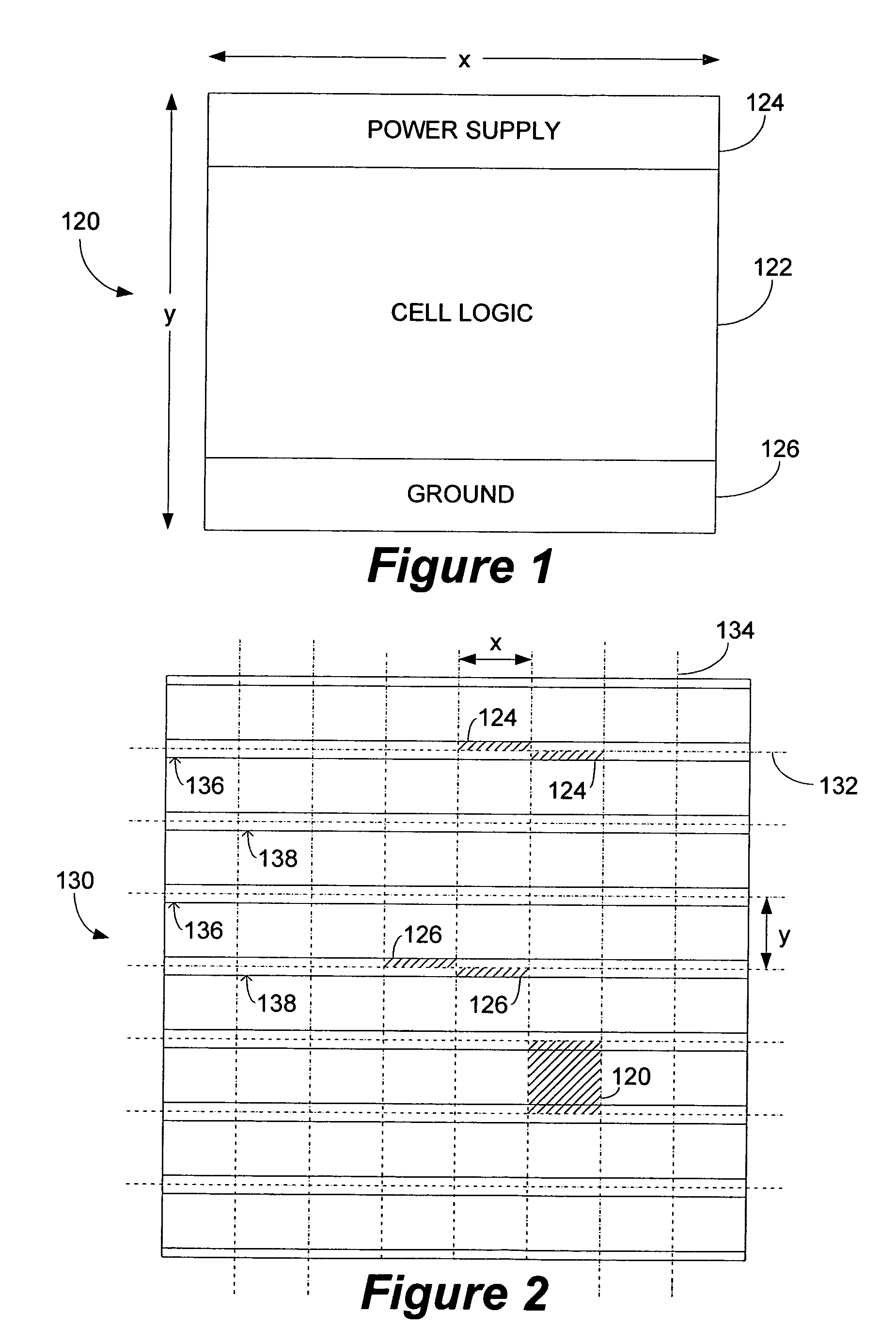
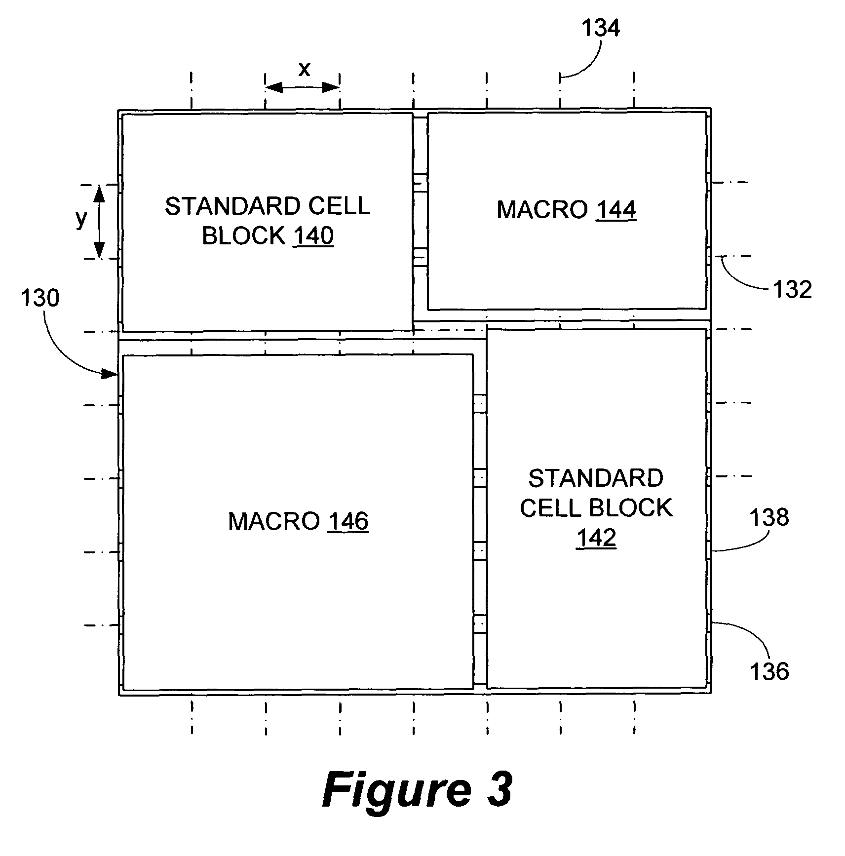
[0024]In platform-based integrated circuit design, circuitry is often expressed in terms of a grid or block comprised of a plurality of standard “cells”. FIG. 1 illustrates a standard cell 120 having width x and height y. Standard cell 120 is a fundamental design unit for software-based, automated circuit design or “place and route” tools. It comprises logic area 122, power supply area or rail 124, and ground area or rail 126. Circuitry and logic components such as resistors, transistors, diodes, gates, latches, flip-flops and so on are formed in the device layers of logic area 122. The device layers are formed above the substrate and are comprised of polycrystalline, diffusion or active, and implant layers. Conductors connecting the circuitry components are formed in the metal layers above the device layers in area 122. Power supply rail 124 is typically positioned along one edge of cell 120 and delivers a relatively higher voltage from the microchip power supply (not shown) to the...


PUM


Abstract

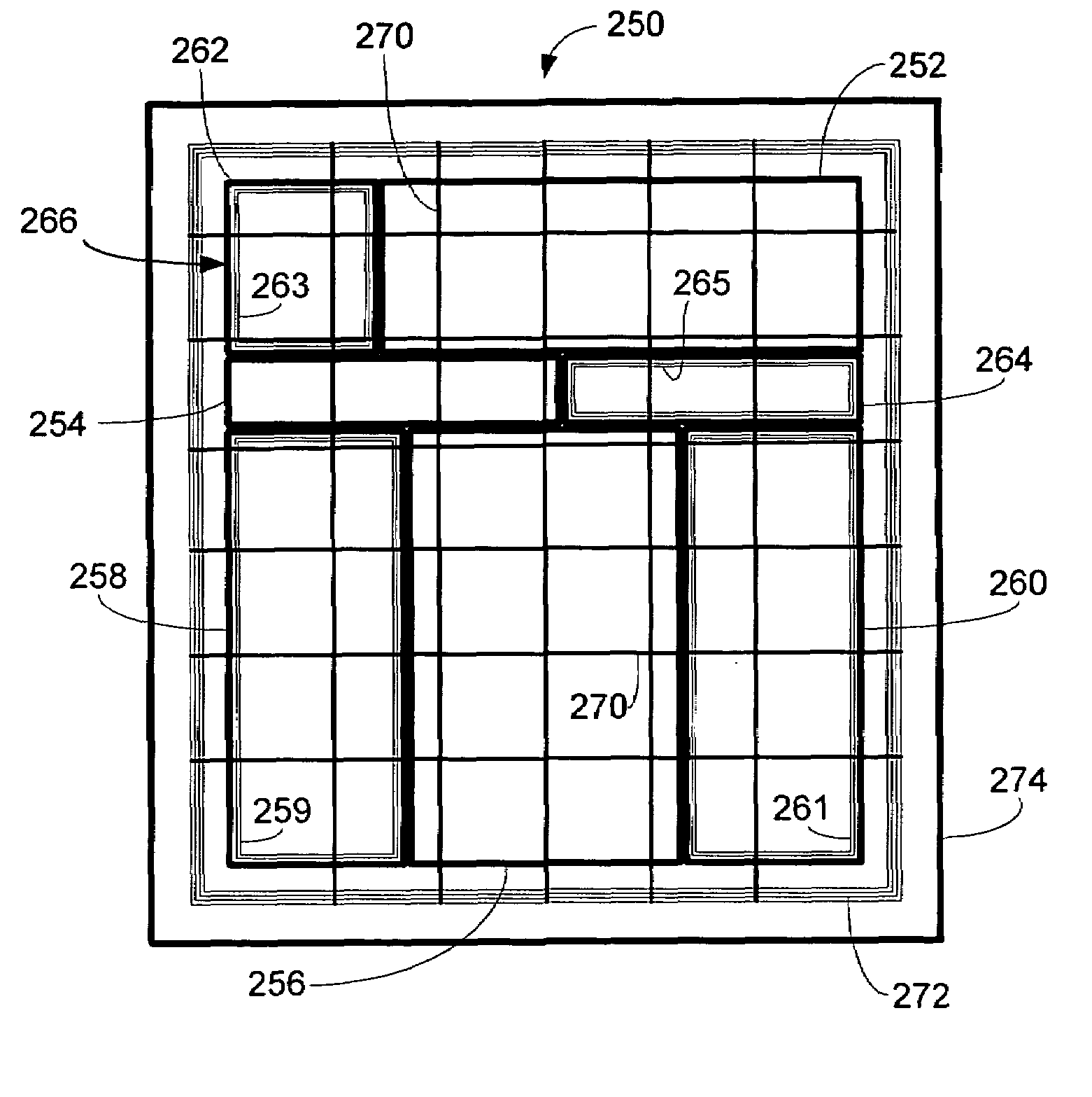
A system and method for routing power between circuit blocks in an integrated circuit, such as macros and standard cells. A macro is wrapped in a relatively narrow power interface ring and placed in the integrated circuit such that the lower metal layers of the power interface ring are aligned and in direct contact with the power rails of a standard cell block. A power grid is formed above the macro and the upper metal layers of the power interface ring are coupled to the power grid. The upper power grid is tied either to an outer power bus or directly to power pins in the surrounding I / O ring. Data signals may be routed in the I / O ring space.

Description

FIELD OF THE INVENTION[0001]The present invention relates to integrated circuit design and, more particularly, relates to a method and apparatus for efficient power routing in a platform-based integrated circuit design environment.BACKGROUND OF THE INVENTION[0002]Platform-based design is becoming a preferred methodology for integrated circuit implementation as the semiconductor industry attempts to keep pace with increasing circuit complexity. The basic idea behind platform-based design is to avoid the need to design a semiconductor chip from scratch. A library of generic blocks or components is defined and designed for easy implementation and reuse as a sub-component of a complete chip design.[0003]There are several approaches to platform-based integrated circuit design. One approach is the “standard cell” approach. A standard cell comprises a plurality of circuitry components such as resistors, transistors, etc., and has a predefined and uniform geometry and pin layout. Standard c...

Claims


Application Information

Patent Timeline
Patent Type & Authority Patents(United States)
IPC IPC(8): G06F17/50
CPCG06F17/5077G06F30/394
Inventor LONGWAY, CHARLES W.RANJAN, RAVISANGHANI, DEVAL D.GOLSHAN, KHOSROW
Owner SYNAPTICS INC
Learn More