Engine oxygen concentration sensor mounting structure

a sensor and oxygen concentration technology, applied in the direction of machines/engines, electric control, instruments, etc., can solve the problems of degradation of oxygen concentration detection accuracy, short exhaust single pipe extending to the rear side of the vehicle body, etc., and achieve the effect of enhancing durability

Inactive Publication Date: 2005-08-09
HONDA MOTOR CO LTD
View PDF11 Cites 12 Cited by
  • Summary
  • Abstract
  • Description
  • Claims
  • Application Information

AI Technical Summary

Benefits of technology

[0008]In accordance with this arrangement, because the oxygen concentration sensor is mounted in the curved collector exhaust pipe extending to the outlet of the exhaust manifold and, when a straight line is drawn from the detection part of the oxygen concentration sensor so as to be parallel to the section of the centerline of the collector exhaust pipe closest to the detection part, this straight line passes outside the outlet of the exhaust manifold, the exhaust gases discharged from the exhaust manifold can be adequately mixed within the curved collector exhaust pipe, thus compensating for differences in the lengths of the plurality of exhaust single pipes and thereby ensuring accurate detection by the oxygen concentration sensor. The adequate mixing of the exhaust gases within the collector exhaust pipe can be achieved by the exhaust gases impinging on the inner wall of the curved exhaust pipe and being diffused, where the inner wall faces the outlet of the exhaust manifold.
[0010]In accordance with this arrangement, because the oxygen concentration sensor is mounted on the inside of the curve of the collector exhaust pipe, the oxygen concentration sensor can be placed by effectively utilizing the dead space formed by the curve in the collector exhaust pipe, thereby enhancing space efficiency. Moreover, it is possible to secure working space for the oxygen concentration sensor to be installed and removed, thereby enhancing ease of maintenance.
[0012]In accordance with this arrangement, because the oxygen concentration sensor is disposed on the front side of the collector exhaust pipe, the oxygen concentration sensor can be cooled by the passage of air as the vehicle travels, thereby enhancing durability.

Problems solved by technology

However, in a multicylinder engine in which the crankshaft is placed lengthwise in the longitudinal direction, an exhaust single pipe extending to a combustion chamber on the front side of the vehicle body inevitably becomes long, and an exhaust single pipe extending to a combustion chamber on the rear side of the vehicle body inevitably becomes short.
As a result, when an oxygen concentration sensor is provided in a collector exhaust pipe connected to the downstream side of the combined part of an exhaust manifold, variations are produced in the levels contributed to the oxygen concentration by the exhaust gases discharged from the combustion chambers, leading to a problem of degradation of the accuracy in detection of the oxygen concentration.

Method used


Image

  • Engine oxygen concentration sensor mounting structure
  • Engine oxygen concentration sensor mounting structure
  • Engine oxygen concentration sensor mounting structure

Examples


Embodiment Construction

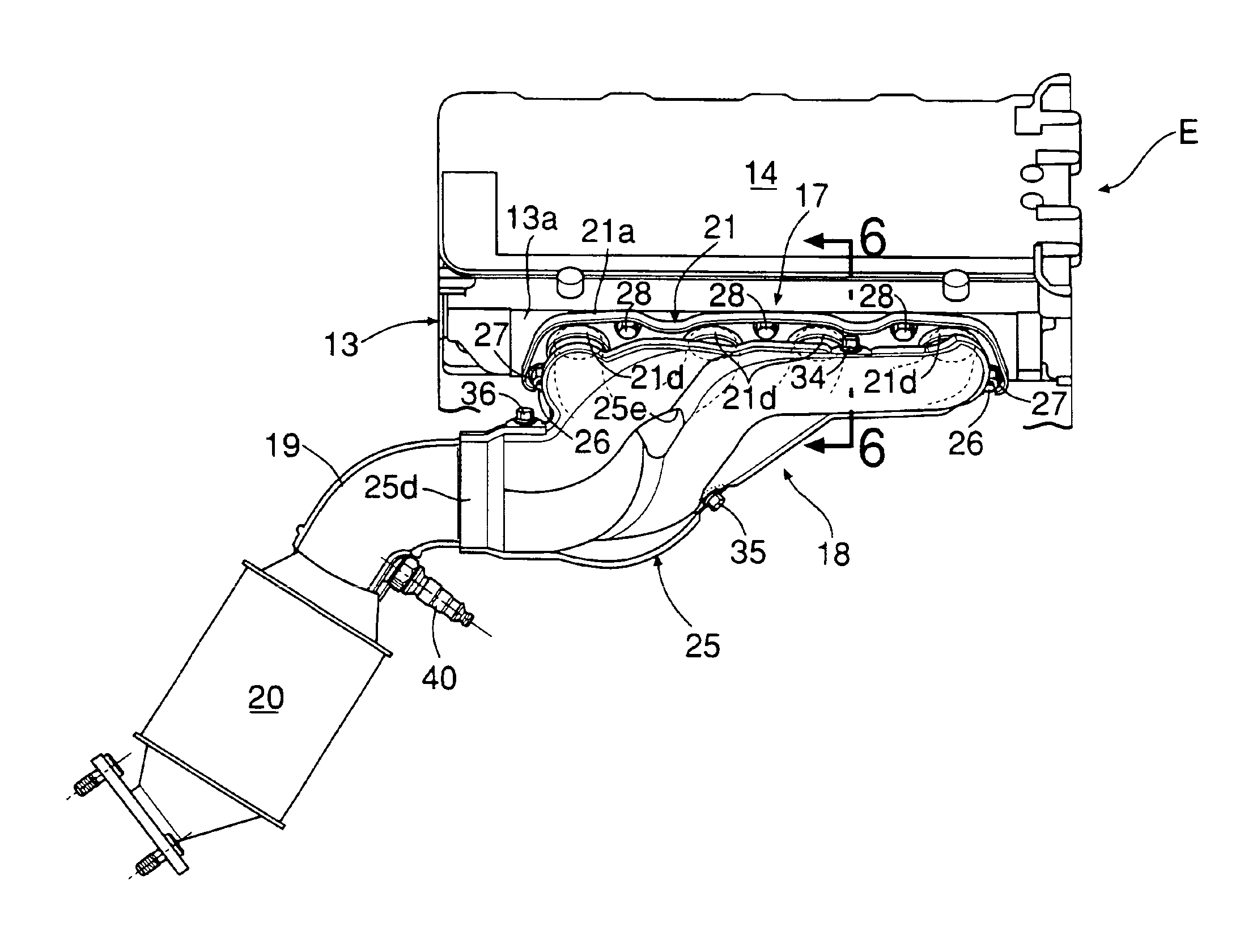
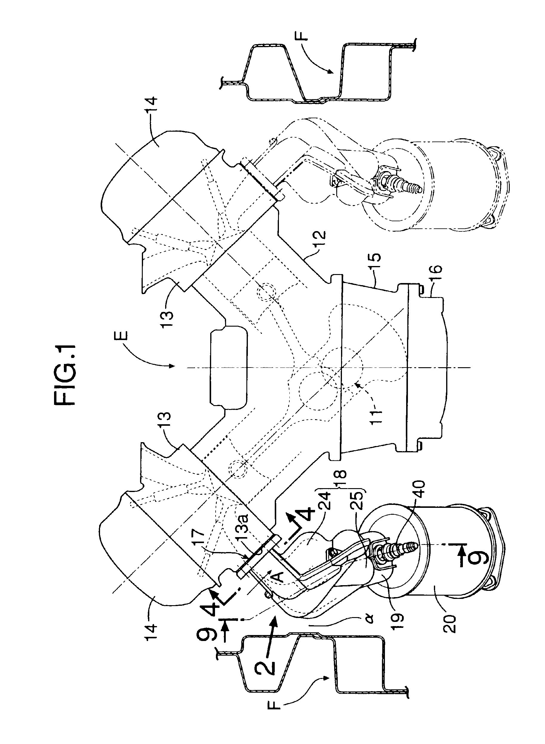
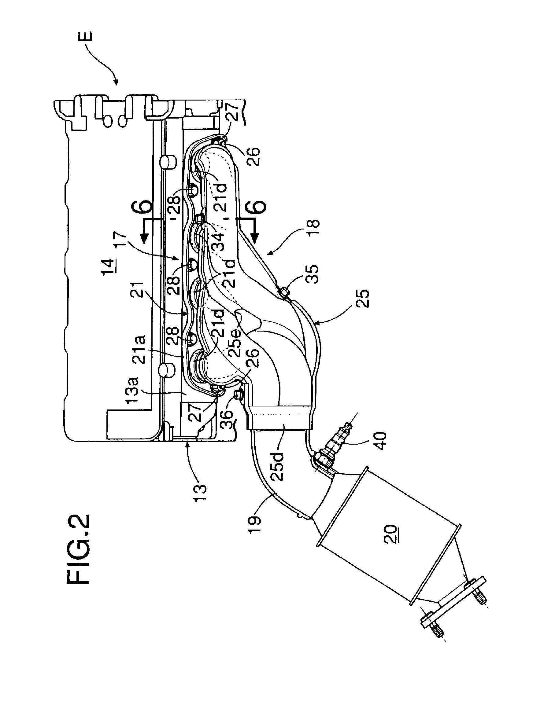
[0025]Referring to FIG. 1, a V-type eight-cylinder engine E is mounted lengthwise in an engine compartment of an automobile so that a crankshaft 11 is disposed in the longitudinal direction of a vehicle body. The engine E includes a V-type cylinder block 12, a pair of left and right cylinder heads 13 joined to the upper faces of the cylinder block 12, a pair of left and right head covers 14 joined to the upper faces of the two cylinder heads 13, a crankcase 15 joined to the lower face of the cylinder block 12, and an oil pan 16 joined to the lower face of the crankcase 15. Joined to mounting faces 13a of the left and right cylinder heads 13 are exhaust manifolds 17, which are enclosed by covers 18. Underneath-type exhaust gas catalytic purification devices 20 are joined to the downstream of the left and right exhaust manifolds 17 via short collector exhaust pipes 19. Left and right front side frames F are disposed in the longitudinal direction so as to be in the proximity of the out...


PUM


Abstract

An engine oxygen concentration sensor mounting structure in which an oxygen concentration sensor is mounted in a collector exhaust pipe connected to an outlet of an exhaust manifold having a plurality of exhaust single pipes. When a straight line is drawn from a detection part of the oxygen concentration sensor positioned within the collector exhaust pipe so as to be parallel to a section of a centerline of the exhaust pipe closest to the detection part, the straight line passes outside the outlet of the exhaust manifold. This allows the exhaust gases discharged from the exhaust manifold to be sufficiently mixed within the curved exhaust pipe and differences in length of the plurality of the exhaust single pipes to be compensated for. Thus, accurate detection by the oxygen concentration sensor can be secured, even if the lengths of a plurality of exhaust single pipes of the exhaust manifold are nonuniform.

Description

BACKGROUND OF THE INVENTION[0001]1. Field of the Invention[0002]The present invention relates to an engine oxygen concentration sensor mounting structure in which an oxygen concentration sensor is mounted in an exhaust pipe connected to an outlet of a collector exhaust manifold of an engine.[0003]2. Description of the Related Art[0004]Conventionally known is a technique of detecting the oxygen concentration of an exhaust gas from an engine by an oxygen concentration sensor and controlling the amount of fuel injected into the engine based on the detected oxygen concentration. In a conventional multicylinder engine, an oxygen concentration sensor is generally provided in a collector exhaust pipe connected to the downstream side of a combined part of an exhaust manifold. In this case, it is known that equalizing the lengths of a plurality of exhaust single pipes forming the exhaust manifold can balance the contribution levels of the exhaust gases discharged from each of the combustion ...

Claims


Application Information

Patent Timeline
Patent Type & Authority Patents(United States)
IPC IPC(8): F01N7/00F01N7/10F01N7/18F01N7/08F01N3/00F01N13/00F01N13/10F01N99/00F02D35/00
CPCF01N13/008F01N13/08F01N13/102F01N13/1805F01N13/1888F01N2260/18F01N2450/22F01N2450/24
Inventor FUJITA, HIROYUKIKAWANAKA, KATSUHIKO
Owner HONDA MOTOR CO LTD
Why Eureka
Try Eureka