Hole reaming apparatus and method

a technology of reaming apparatus and reamer, which is applied in the direction of shaft equipment, shaft lining, slitting machines, etc., can solve the problems of lengthening the useful life of the reamer, and achieve the effects of quick drilling, low incidence of stoppage for unplugging or replacement, and little wear

Inactive Publication Date: 2005-08-09
XTECH INDS INT
View PDF24 Cites 24 Cited by
  • Summary
  • Abstract
  • Description
  • Claims
  • Application Information

AI Technical Summary

Benefits of technology

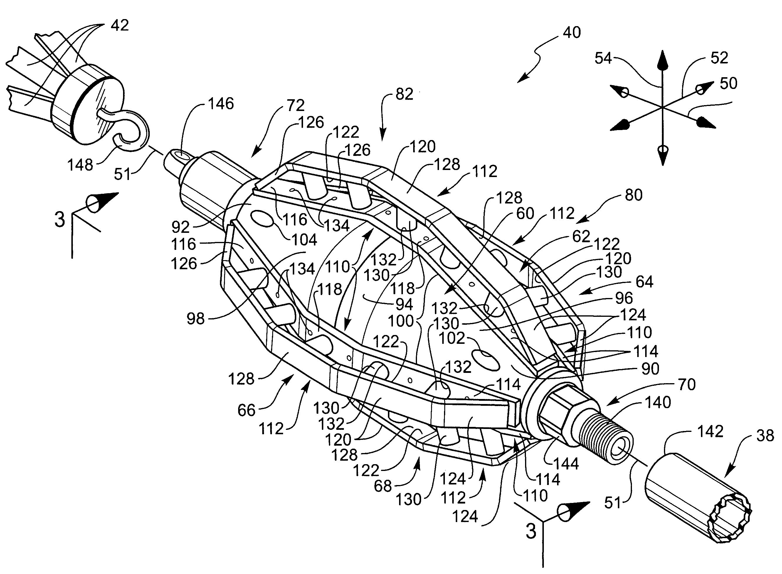
[0011]The apparatus and method of the present invention have been developed in response to the present state of the art, and in particular, in response to the problems and needs in the art that have not yet been fully solved by currently available reaming systems and methods. Thus, it is an overall purpose of the present invention to provide reaming systems and methods capable of rapidly drilling a hole with little wear and a low incidence of stoppage for unplugging or replacement.

Problems solved by technology

Thus, the orientation of the reamer can be reversed to equalize wear on both ends of the reamer, thereby lengthening the useful life of the reamer.

Method used


Image

  • Hole reaming apparatus and method
  • Hole reaming apparatus and method
  • Hole reaming apparatus and method

Examples


Embodiment Construction

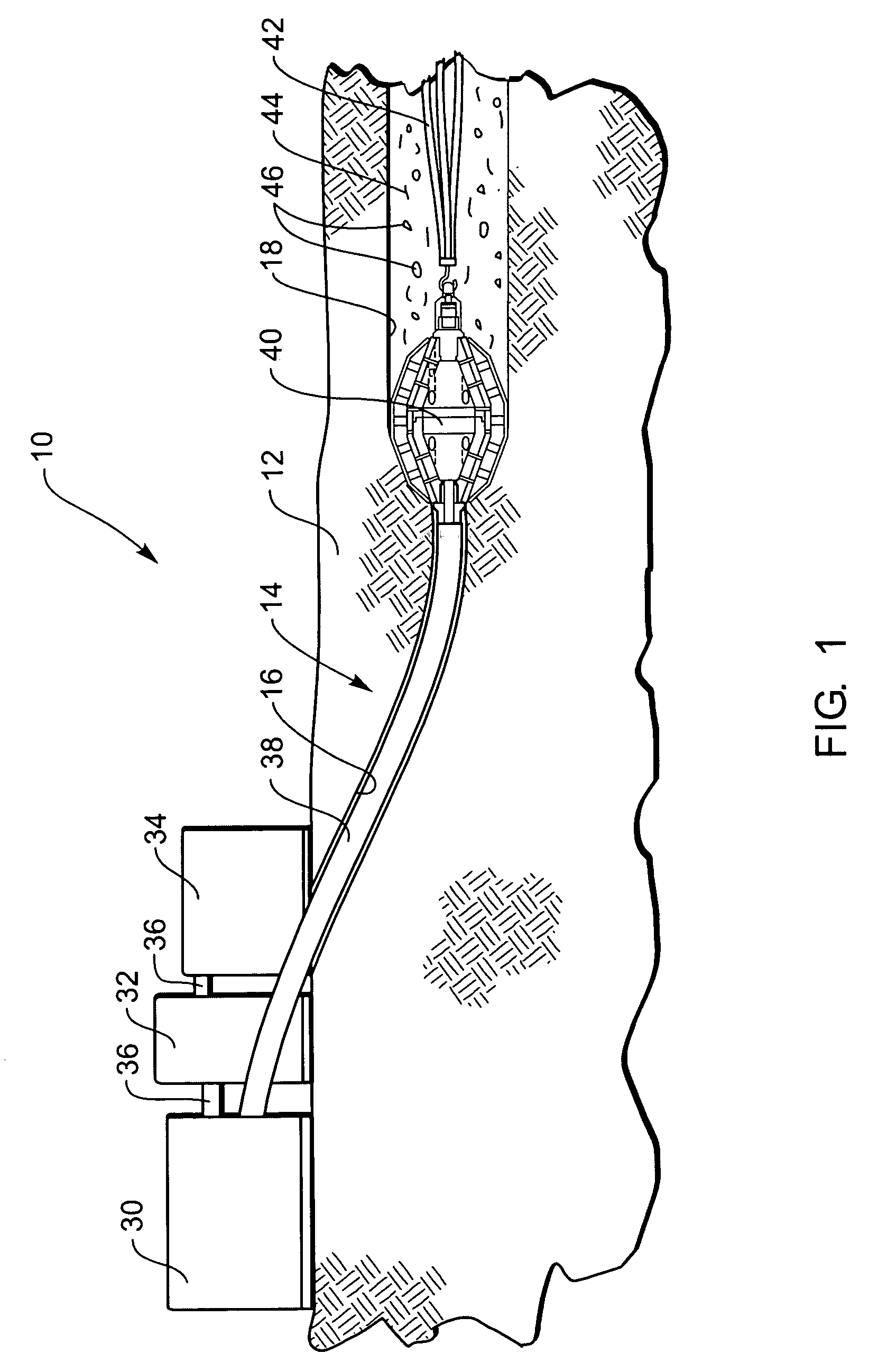
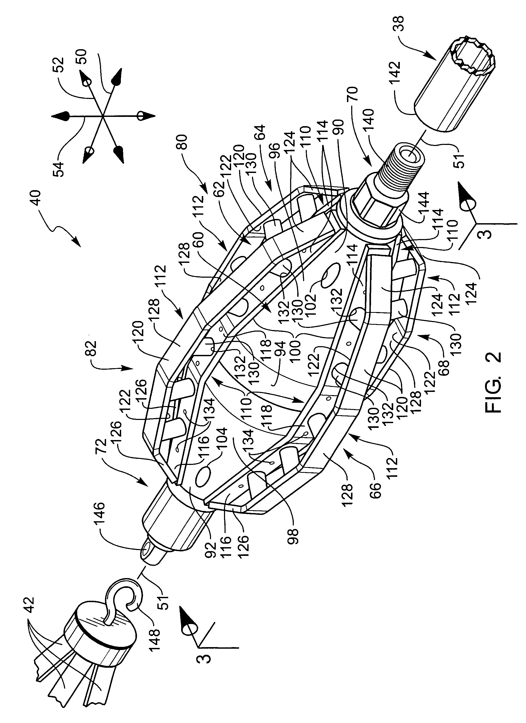
[0039]The presently preferred embodiments of the present invention will be best understood by reference to the drawings, wherein like parts are designated by like numerals throughout. It will be readily understood that the components of the present invention, as generally described and illustrated in the figures herein, could be arranged and designed in a wide variety of different configurations. Thus, the following more detailed description of the embodiments of the apparatus, system, and method of the present invention, as represented in FIGS. 1 through 7, is not intended to limit the scope of the invention, as claimed, but is merely representative of presently preferred embodiments of the invention.

[0040]For this application, the phrases “connected to,”“coupled to,” and “in communication with” refer to any form of interaction between two or more entities, including mechanical, electrical, magnetic, electromagnetic, and thermal interaction. The phrase “attached to” refers to a for...


PUM


Abstract

An enhanced reaming apparatus and method are disclosed. A reaming assembly may have a motor and a pump that provide linear force, torsional force, and pressurized drilling fluid to a reamer to cause the reamer to enlarge the bore of a pilot hole. The reamer may have a body and a plurality of blade assemblies that cooperate to define two substantially symmetrical, oppositely oriented reaming sections. Each blade assembly may have an inner blade attached to the body and an outer blade extending outward from the body. Hard cutting elements may be used in place of the outer blade. The blade assemblies may be field-replaced, or the orientation of the reamer may be reversed to enhance the life of the reamer. The reamer has jets and circulation openings that release the drilling fluid into the bore to facilitate penetration and remove cuttings.

Description

RELATED APPLICATIONS[0001]This application claims the benefit of U.S. Provisional Application No. 60 / 363,745 filed Mar. 12, 2002 and entitled CLAY REAMER FOR HORIZONTAL DIRECTIONAL DRILLING, which is incorporated herein by reference.BACKGROUND OF THE INVENTION[0002]1. Field of the Invention[0003]The present invention relates to systems and methods for drilling in the earth. More specifically, the present invention relates to enhanced reaming assemblies and methods for use in horizontal directional drilling.[0004]2. Description of Related Art[0005]In many circumstances, it is desirable to form a hole along a controllable path. For example, when utility lines are to be laid underneath a road, building, or other structure, it may be desirable to drill a generally horizontal hole in the ground rather than forming a trench in which to lay the utility lines. This type of drilling is commonly referred to as “horizontal directional drilling,” or “HDD.”[0006]According to some known horizonta...

Claims


Application Information

Patent Timeline
Patent Type & Authority Patents(United States)
IPC IPC(8): E21B7/00E21B7/28E21B10/26
CPCE21B7/28E21B10/26E21C35/197
Inventor ANTHONY, PAUL G.PIERSON, MILES G.
Owner XTECH INDS INT
Why Eureka
Try Eureka