Extended range, light weight laser target designator

a laser target and light weight technology, applied in direction controllers, direction/deviation determining electromagnetic systems, instruments, etc., can solve the problems of reducing countermeasure effectiveness, doublet pulse laser target designators suffer from the disadvantage of almost twice the laser energy per doublet pair, etc., and achieve the effect of increasing the signal-to-noise ratio in seekers

Inactive Publication Date: 2005-08-09
BAE SYST INFORMATION & ELECTRONICS SYST INTERGRATION INC +1
View PDF4 Cites 65 Cited by
  • Summary
  • Abstract
  • Description
  • Claims
  • Application Information

AI Technical Summary

Benefits of technology

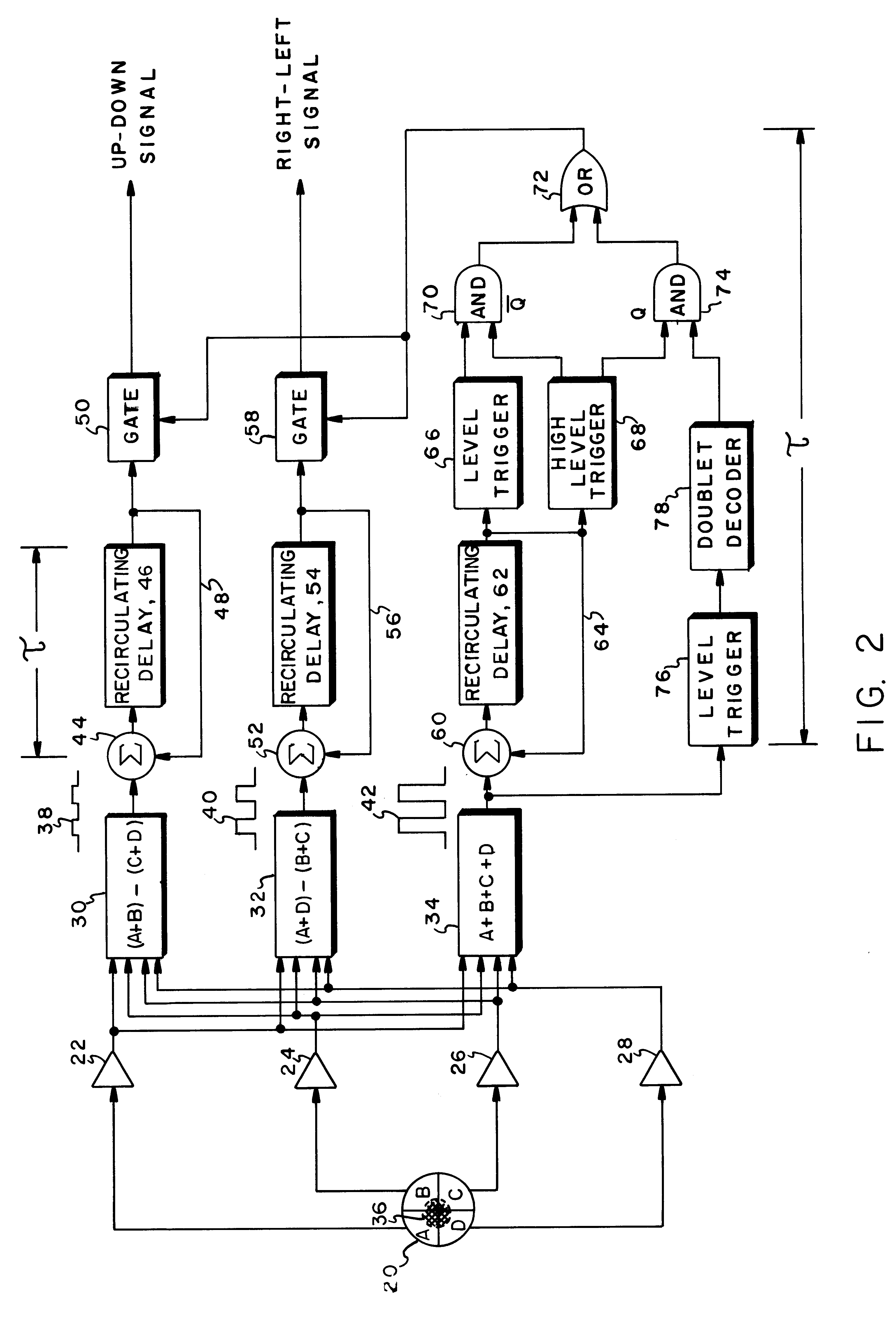
[0015]Alternatively, the pulse integration system may be completely taken out of the loop once the doublet mode threshold has been reached. This may have some advantages in close range situations where the signal-to-noise ratio is sufficiently high. However, it will be appreciated that by utilization of the recirculating delay units in the first two channels, an even higher signal-to-noise ratio can be obtained in these channels, with a consequent reduction in the false alarm rate.
[0017]It is therefore an object of this invention to provide an improved target designating system utilizing pulse integration for extending the range of the system;
[0019]It is another object of this invention to provide a method and apparatus for increasing the signal-to-noise ratio in seekers utilized with multiple pulse target designating systems.

Problems solved by technology

Doublet pulse laser target designators suffer from the disadvantage of requiring almost twice the laser energy per doublet pair,in order to provide range performance equal to a single pulse system.
However, in the extended range mode, countermeasure effectiveness is minimized, since even if countermeasuring is employed, the missile will, nonetheless, approach the target.

Method used


Image

  • Extended range, light weight laser target designator
  • Extended range, light weight laser target designator
  • Extended range, light weight laser target designator

Examples


Embodiment Construction

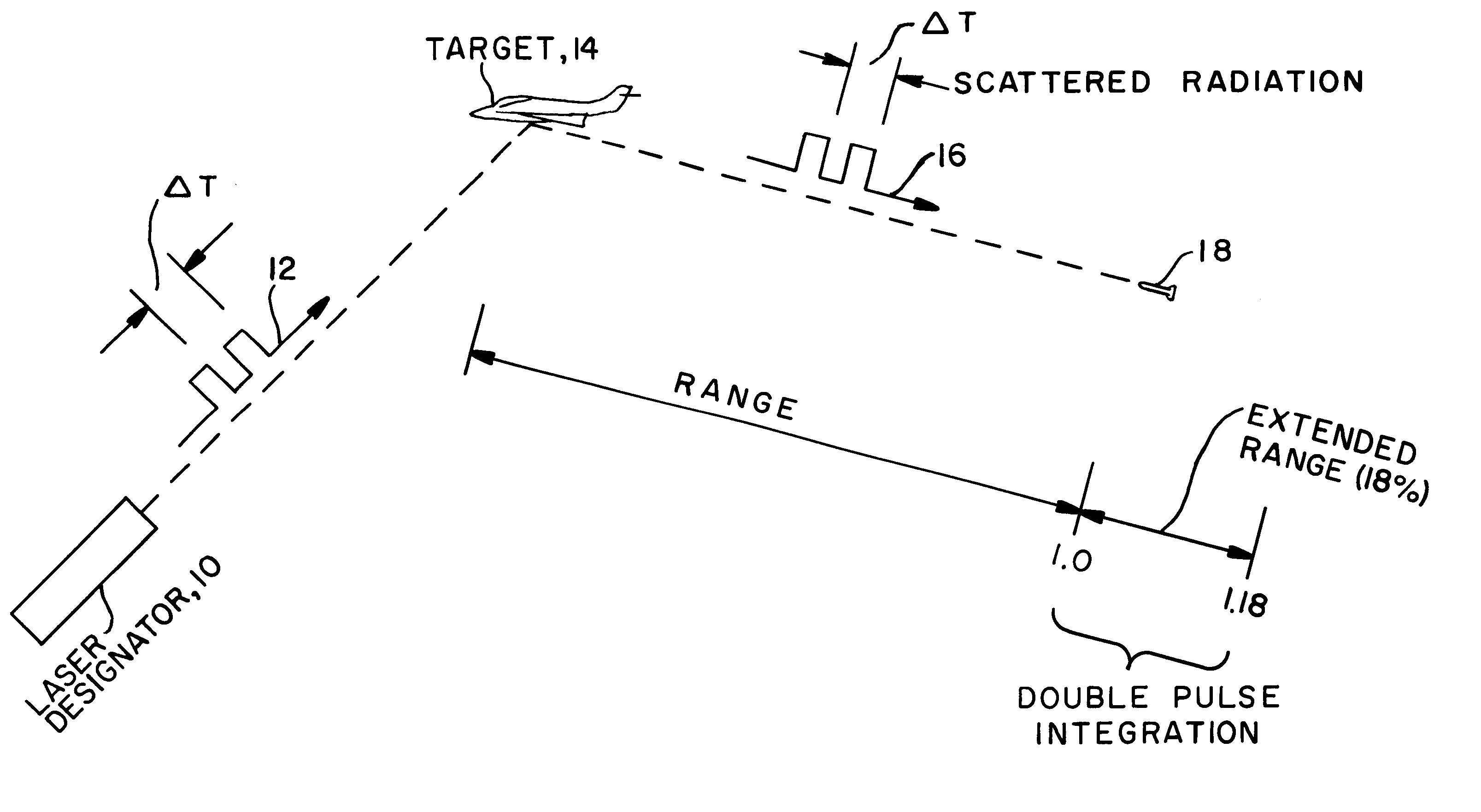
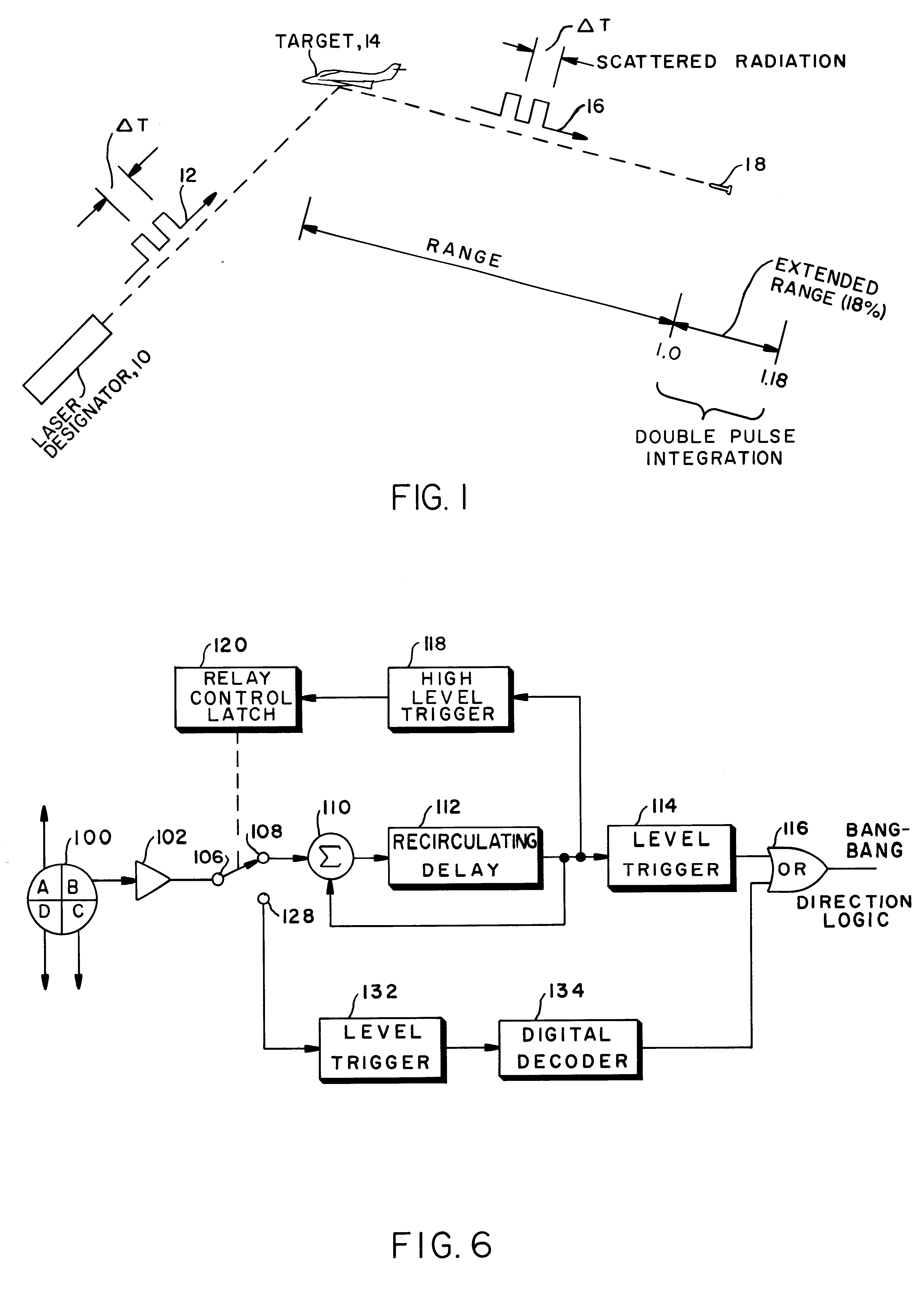
[0027]Referring now to FIG. 1, a typical laser target designator system is depicted in which a source of multiple pulses, such as a laser 10, directs a pulse doublet 12 with an interpulse delay ΔT towards a target 14. The target scatters the light from the laser in all directions and scattered radiation in the form of a pulse doublet 16 propagates in the direction of a missile or guided ordinance device 18. Under ordinary circumstances, without pulse integration, the seeker aboard missile 18 would acquire the target at a normalized range 1.0 as illustrated. With the system to be described, target acquisition would take place at an extended range such as that illustrated, which in the doublet pulse case, is on the order of a 18% increase. In one embodiment, the normalized range defines a range perimeter with the target at its center. It is the function of the subject circuit to provide pulse integration circuitry at points outside the range perimeter, while activating doublet decodin...


PUM


Abstract

Pulse integration is utilized on board an optically guided missile or other ordinance device used as a part of a target designation system for extending the lock-on range of the missile by approximately 18%, when a double pulse laser is utilized to illuminate and designate the target. Pulse integration is accomplished with a recirculating delay unit which superimposes the first pulse on the second pulse, such that while the pulses add coherently, noise does not add in phase. The pulse integration technique therefore enhances the signal-to-noise ratio when the missile is at the outer limits of its operating range. When the missile is sufficiently close to the target, doublet decoding is actuated to offer countermeasure resistance. At this point, pulse integration may proceed in lieu of doublet decoding or may be dispensed with in view of the increased signal-to-noise ratio due to the close range of the missile to the target.

Description

FIELD OF THE INVENTION[0001]This invention relates to target designators, and more particularly, to a method and apparatus for extending the range of a target designator.BACKGROUND OF THE INVENTION[0002]Target designators, usually employing lasers, have in the past made use of a so-called “doublet pulse”, a pulse burst containing two pulses, in which the inter-pulse spacing is varied to provide a code which can be recognized by incoming missiles, guided shells or other ordinance devices. Doublet pulse laser target designators suffer from the disadvantage of requiring almost twice the laser energy per doublet pair,in order to provide range performance equal to a single pulse system.[0003]In a recent development, a large portion of the extra energy requirement is compensated for by the superior efficiency provided by multi-cavity single-pump lasers or single-pump multi-laser systems in which sequentially activated Q-switches are provided in the laser-cavities. In these lasers a single...

Claims


Application Information

Patent Timeline
Patent Type & Authority Patents(United States)
IPC IPC(8): F41G7/00G01S5/16G01S5/00G01S7/28G01S3/783G01S7/486
CPCF41G7/226F41G7/2293G01S3/783G01S7/486
Inventor YOUNG, DONALD S.MISEK, VICTOR A.
Owner BAE SYST INFORMATION & ELECTRONICS SYST INTERGRATION INC
Why Eureka
Try Eureka