Hoist system

a technology of hoist system and running trolley, which is applied in the direction of hoisting equipment, mechanical equipment, drilling pipes, etc., can solve the problems of reducing the useful work that can be done with the running trolley, affecting the safety of the hoist, so as to reduce the chance of personal injury, and the effect of less tim

Inactive Publication Date: 2005-08-09
ITREC BV
View PDF10 Cites 59 Cited by
  • Summary
  • Abstract
  • Description
  • Claims
  • Application Information

AI Technical Summary

Benefits of technology

[0009]An advantage of the invention is that hoisting means can be provided with two winches, each end of the hoisting cable being wound onto a separate winch. By winding the two ends onto a separate winch, it is possible to achieve the same cable speed at a relatively low speed of revolution of the winches. By using two winches the cable can be shifted automatically a distance from one winch to the other winch. This method effectively replaces the “slip & cut” procedure. This alternative method takes considerably less time and can be performed completely automatic reducing the chance of personal injuries.
[0010]Moreover, by adding the second winch, redundancy is provided in the system. If one of the winches fails, the hoist system is still usable and work can continue with a single winch.
[0011]The winches can be driven by a plurality of relatively small motors; therefore, twice as many sides of the winches can be used to attach the motor on the winch. These winch motors can be relatively small. For example, it is possible to equip the winches on both sides with electric motors that engage with a pinion in a toothed wheel of the winch. The first advantage of this is that such electric motors are commercially available. For the use in the hoist system, it is not necessary to develop a special and expensive hoisting winch. The second advantage is that the relatively small motors have a low internal inertia. The low inertia means that when the direction of rotation of the winch is reversed less energy and time are lost during the reversal.
[0012]In the case of a hoist system according to the prior art of the type mentioned in the preamble, finding the optimum compromise between speed and power is a known problem. The hoisting cable is guided in such a way over the cable blocks in the mast and on the trolley that several cable parts extend between the mast and the trolley. In this case the more wire parts are present between the mast and the trolley; the greater the load that can be lifted with the hoist system if the hoisting winch remains unchanged. However, the more wire parts are present between the mast and the trolley, the lower the speed at which the trolley can be moved relative to the mast when the maximal speed of the winch stays the same.
[0013]In order to find a good compromise between speed and lifting power, it is generally decided to provide the hoist system with relatively heavy winches. The heavy winches are designed to ensure that the rapid movement of the trolley up and down can be met in every case. This also means, however, that a substantial part of the lifting power is not being utilized for a substantial part of the time. In other words, the device is actually provided with winches that are too heavy—and therefore too expensive—to be able to reach sufficient speed occasionally.
[0014]Another object of the present invention to provide a hoist system of the type mentioned in the preamble. On the one hand, a relatively heavy load can be lifted and, on the other hand, a relatively light load can be operated at a relatively high speed. This type of design means winches and motors are relatively light and cheap.

Problems solved by technology

These tracks must be supported in order to avoid unwanted movements of the running trolley; however, due to constructional limitations, a certain movement remains.
Since the trolley is usually located inside the derrick, access to the running trolley is severely limited.
This decreases the useful work that can be done with the derrick.
If this winch breaks down, it is no longer possible to work with the device.
The design of the afore-mentioned winch must be relatively large and costly to meet with all the required demands.
This procedure requires considerable time and is also dangerous to the workers.
In the case of a hoist system according to the prior art of the type mentioned in the preamble, finding the optimum compromise between speed and power is a known problem.
However, the more wire parts are present between the mast and the trolley, the lower the speed at which the trolley can be moved relative to the mast when the maximal speed of the winch stays the same.
This also means, however, that a substantial part of the lifting power is not being utilized for a substantial part of the time.
In other words, the device is actually provided with winches that are too heavy—and therefore too expensive—to be able to reach sufficient speed occasionally.
In drilling derricks in the prior art, these special features can only be installed at high cost.

Method used


Image

  • Hoist system
  • Hoist system
  • Hoist system

Examples


Embodiment Construction

[0040]Before explaining the present invention in detail, it is to be understood that the invention is not limited to the particular embodiments and that it can be practiced or carried out in various ways.

[0041]A novel feature of the invention is that the hoist system can be used to lift a heavy load and then a light load, in sequence, quickly, safely and efficiently. Similarly, the invention can be used to lift a plurality of light loads and then quickly modified to lift a plurality of heavy loads. The modifications can be done quickly, easily, and safely at sea, without the hoist system needing to be returned to land for retrofitting.

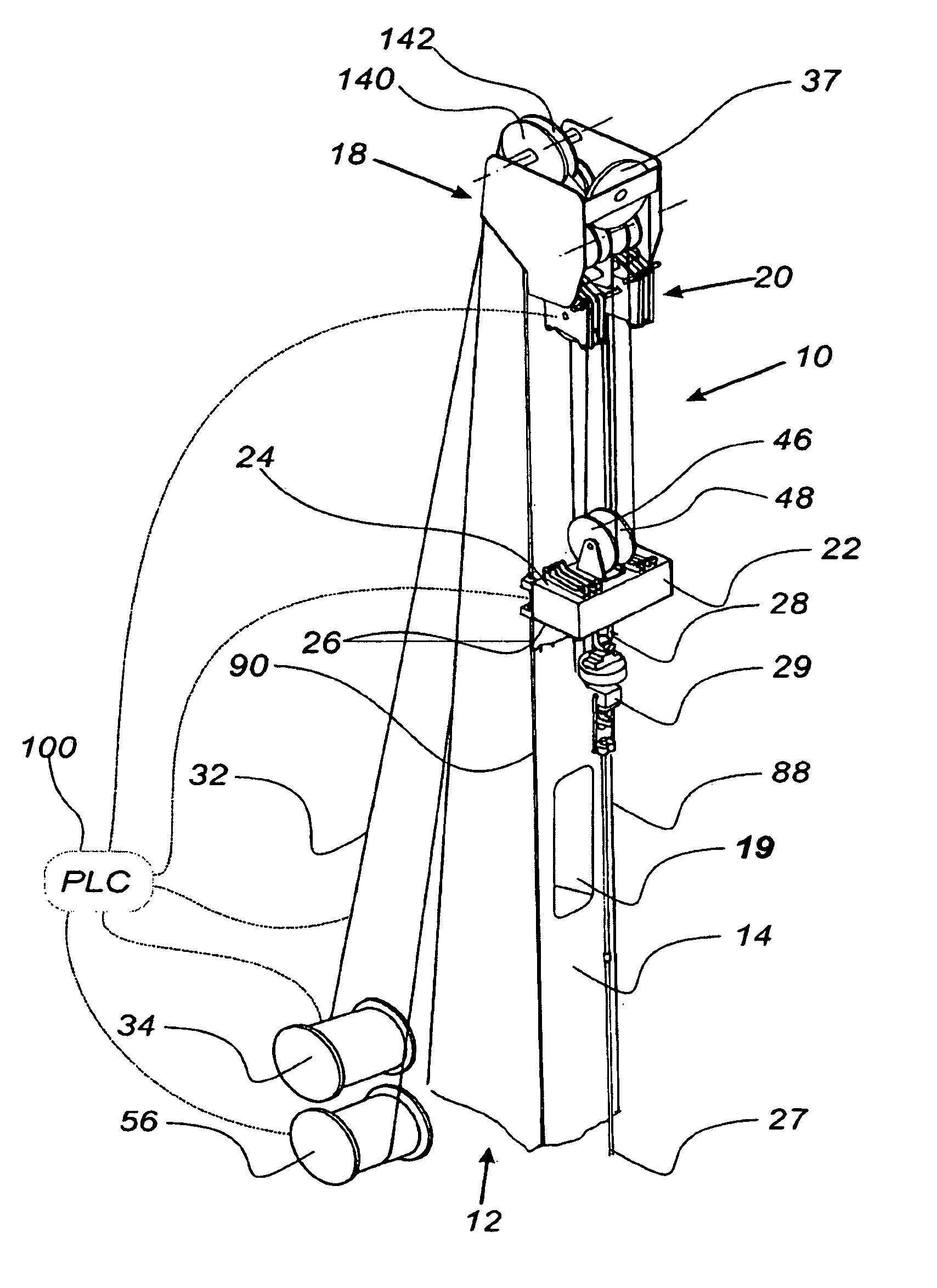
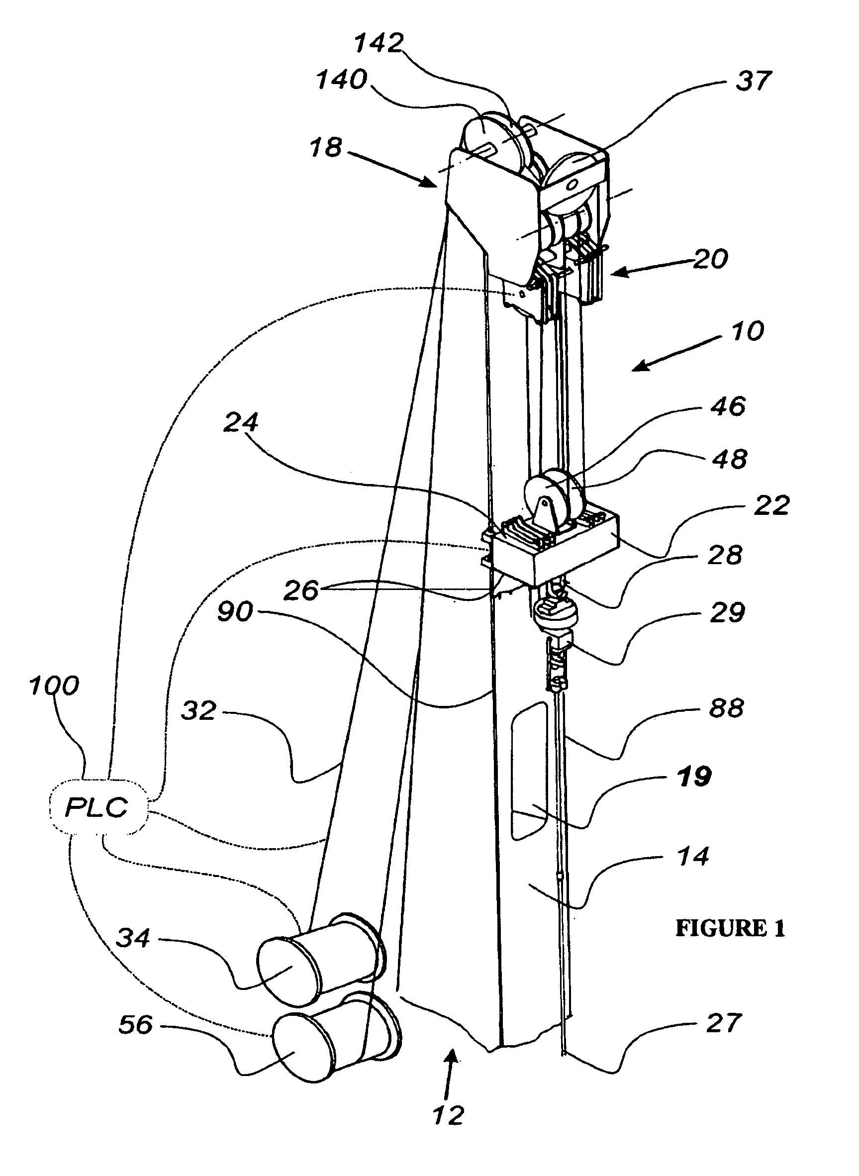
[0042]FIG. 1 shows the hoist system 10 according to the present invention. The hoist system 10 comprises a tubular mast 12. In the description below the term tubular mast will always be used, but it must be understood that any other suitable device, such as, for example, a tower, could also be used. The system is controlled by a control system 100.

[004...


PUM


Abstract

The invention is a hoist system for use on a drilling rig made of a tubular mast with a front, back, and top side, a splittable block connected to the mast top side, a trolley with a trolley top and bottom side, wherein the trolley's top side is connected to the splittable block and wherein the trolley is removably secured on the mast's front side, a gripper connected to the trolley bottom side for gripping a load, a hoist cable passing through the splittable block and connected on one end to a hoist cable winch, and a hoist cable winch adapted to pull the hoist cable over the mast top side and through the splittable block to move the trolley relative to the tubular mast and lift the load.

Description

[0001]The present application claims priority to Pending patent application Ser. No. 09 / 807,078 filed in the U.S. Patent and Trademark Office on Jul. 2, 2001.FIELD OF THE INVENTION[0002]The present invention relates to a hoist system contained inside a tower that minimizes the energy consumption and operating cost of lifting operations.BACKGROUND OF THE INVENTION[0003]Hoist systems, in the prior art, are used in the offshore industry in the form of drilling derricks on, for example, drilling vessels. When, in use, a drill string is attached to the bottom side of a trolley, also known as a traveling block. The trolley runs on a separate track inside the derrick. These tracks must be supported in order to avoid unwanted movements of the running trolley; however, due to constructional limitations, a certain movement remains. Since the trolley is usually located inside the derrick, access to the running trolley is severely limited. This decreases the useful work that can be done with th...

Claims


Application Information

Patent Timeline
Patent Type & Authority Patents(United States)
IPC IPC(8): B66D1/00B66D3/04B66D3/06E21B19/02
CPCB66D3/043B66D3/06E21B19/02
Inventor ROODENBURG, JOOPRODENBURG, ADRIAAN JAN
Owner ITREC BV
Why Eureka
Try Eureka