Aortic balloon occlusion cannula

a technology of aortic balloon and cannula, which is applied in the field of aortic balloon occlusion cannula, can solve the problems of increasing the risk of embolism caused by calcified particles, and achieves the effects of reducing ischemic time, avoiding dangerous tangential clamping of an aortic area, and ensuring the field of surgical operation remains much clearer

Inactive Publication Date: 2005-08-09
MEDICOR
View PDF11 Cites 29 Cited by
  • Summary
  • Abstract
  • Description
  • Claims
  • Application Information

AI Technical Summary

Benefits of technology

[0006]An object of this invention is to offer a solution to the above mentioned problem and to create an aortic balloon occlusion cannula for the occlusion of the ascending aorta during surgeries. This aortic balloon occlusion cannula is adapted to reduce the danger of the separation of calcified plaques from the calcified ascending aorta and to guarantee a careful treatment of the aorta during the surgery.
[0008]Furthermore, the new aortic cannula permits the clamping of the ascending aorta from the inside by means of a dilatable occlusion balloon. In addition, the cannula carries a second occlusion balloon that is positioned in a certain distance from the first balloon. It is able to separate an area from the perfusion. This area is determined by the distance between the two balloons. It serves then for the suture of the vein bypasses. With this, the dangerous tangential clamping of an aortic area is avoided. In the meantime, the aortic root perfusion can retrogradely be performed by means of a coronary sinus in order to reduce the ischemic time.

Problems solved by technology

It is just with an arteriosclerotic aorta ascendens that suturing of the aorta can be a problem which occasionally necessitates a partial clamping of this area resulting in an increased risk of embolies caused by calcified particles.

Method used


Image

  • Aortic balloon occlusion cannula
  • Aortic balloon occlusion cannula
  • Aortic balloon occlusion cannula

Examples


Embodiment Construction

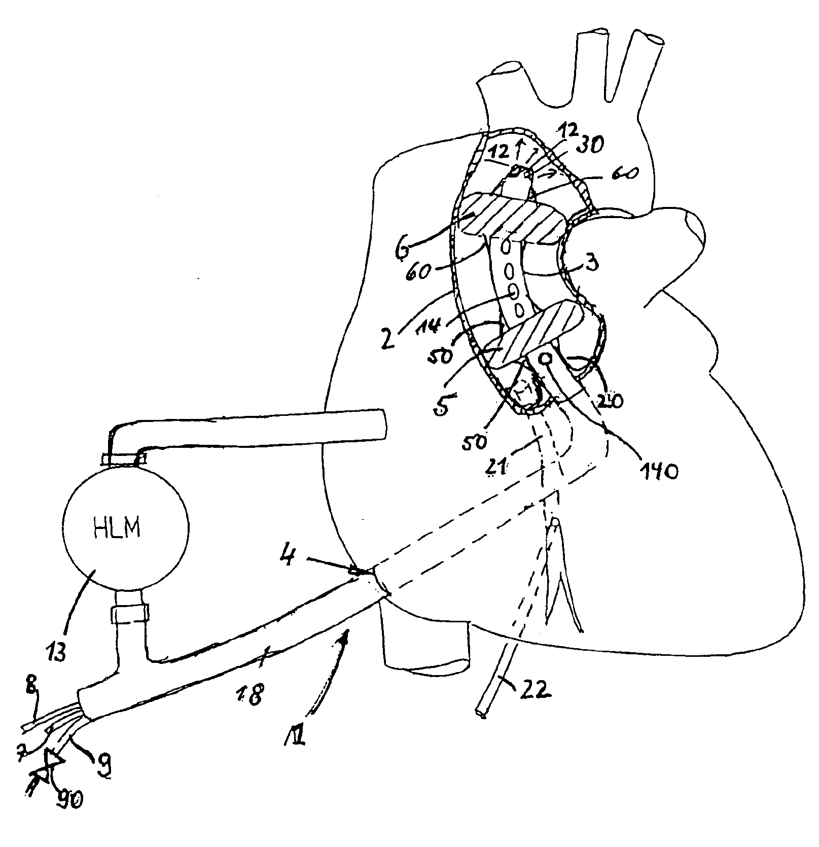
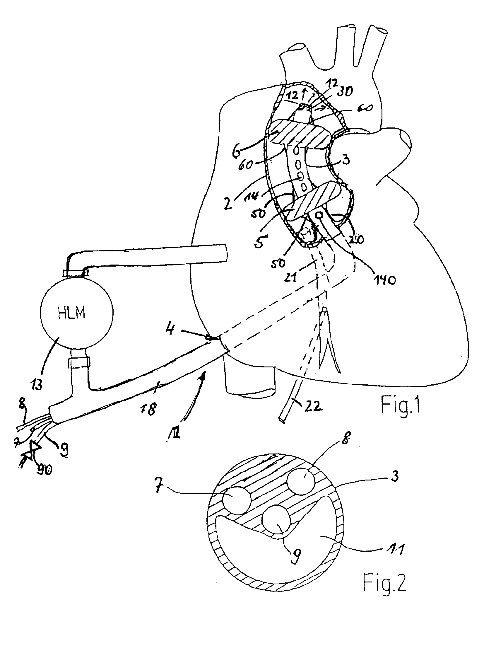
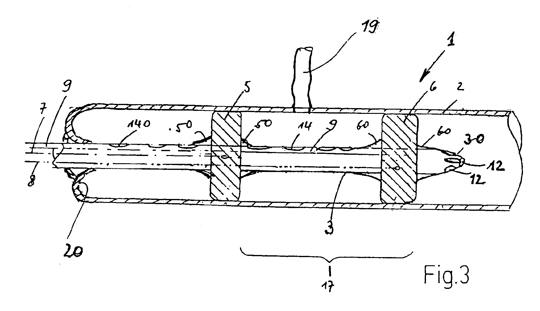
[0014]The aortic balloon occlusion cannula, which is generally marked by a 1, is to occlude the ascending aorta indicated at 2, during cardiac surgeries. It contains a cannula tube 3 that is made out of an elastic material. This material enables the introduction of the cannula tube 3, while adapting to the required curvatures, into the ascending aorta 2 through a corresponding incision at 4 (FIG. 3) in the lefthand cardiac ventricle. When inserting the cannula care must be taken to pass the valvola aortae 20 as carefully as possible. Therefore, in the beginning a guide wire is placed into the heart and subsequently the cannula is inserted by means of a guide rod that is located in the cannula tube 3 and provided with a tapered end. This guide rod defines a lumen for said guide wire and is removed from the cannula tube 3 when the cannula is correctly inserted.

[0015]Cannula tube 3 can also be pre-shaped according to the curvature of the ascending aorta. Two dilatable occlusion balloon...


PUM


Abstract

An aortic balloon occlusion cannula for the occlusion of the aorta ascendens during cardiac surgery including a cannula containing several lumina that are separated from one another. The cannula carriers two dilatable occlusion balloons positioned at a distance from each other, one of the balloons being neighbored to the distal end of the cannula which faces away from the heart and each of the balloons being connected to its own lumen which enables its dilation in independence from the other balloon. The cannula is insertable through the lefthand ventricle of the heart and through the valvula aortae and includes at least one further lumen. The further lumen being connected on the distal side, facing the body, of the distal occlusion balloon to the lumen of the aorta and is adapted to be connected to an extracorporal blood supply device. An additional separate lumen is provided in the cannula and forms a return conduit for liquid and opens on the proximal side of the proximal occlusion balloon.

Description

BACKGROUND[0001]The invention concerns an aortic balloon occlusion cannula for the occlusion of the ascending aorta during cardiac surgery.[0002]An arteriosclerotically altered ascending aorta represents a problem in the field of cardiac surgery. It occurs in almost all patients who suffer from calcification of the coronary vessels or, to different degrees, in patients with valvular diseases. It is necessary to insert an aortic cannula into the ascending aorta in order to connect for instance a patient, who undergoes a bypass operation, to the extra corporal circulation (heart-lung machine). The blood circulation is separated from the heart by clamping the ascending aorta towards the heart that is proximal, with a metal clamp, which is attached at right angles. There is, however, the danger of a detachment of particles or plaques from the wall of the ascending aorta which are transported by the blood flow especially into the blood vessels of the head and therefore into the brain. Th...

Claims


Application Information

Patent Timeline
Patent Type & Authority Patents(United States)
IPC IPC(8): A61B19/00A61M29/00A61M1/36A61M37/00
CPCA61M1/3653A61M1/3666A61M25/0032A61M25/1011A61M25/104A61M25/0041A61M25/0068A61M2025/0031A61M2025/004A61M2025/1015A61M2025/1052A61M2025/1095A61M1/3659A61M1/3613
Inventor SCHEULE, ALBERTUS
Owner MEDICOR
Why Eureka
Try Eureka