Multi-lumen vascular grafts having improved self-sealing properties

a multi-lumen, vascular graft technology, applied in the direction of prosthesis, blood vessels, coatings, etc., can solve the problems of affecting the healing effect of the graft, so as to achieve the effect of improving healing effect, and reducing the risk of recurren

Inactive Publication Date: 2005-08-09
MAQUET CARDIOVASCULAR LLC
View PDF23 Cites 92 Cited by
  • Summary
  • Abstract
  • Description
  • Claims
  • Application Information

AI Technical Summary

Benefits of technology

[0017]One advantage of the present invention is that there is provided a vascular graft having sufficient porosity, flexibility and strength to use in procedures requiring repeated needle access and which includes a self-sealing capability.
[0018]Another advantage of the present invention is that the inventive vascular grafts can be used within a short period of time after implantation without adverse impact to the integrity of the graft.
[0019]A still further advantage of the present invention is that the inventive grafts are easily and reliably manufactured.
[0020]Another advantage of the present invention is that the inventive grafts provide superior assimilation capabilities and resealable properties.
[0021]It is a further advantage of the present invention that a self-sealing graft is provided which performs a drug delivery function.
[0022]Briefly stated, the present invention provides an implantable graft, including a primary tubular body having a first outer wall surface and a first inner wall surface defining a primary blood contacting lumen; and a secondary tubular body having a second outer wall surface and a second inner wall surface. The secondary tubular body is located about the primary tubular body to form a space therebetween. The primary and secondary tubular bodies are joined by at least one rib.

Problems solved by technology

Such damage or dysfunction can arise, for example, from arterial or venous pathways that have been damaged by thrombosis, an aneurysm or occlusion.
Natural blood vessels are often damaged during treatment of renal failure.
As a result of the repeated percutaneous access, the vein will often collapse along the puncture tract or become aneurismal, leaky, or filled with clot.
The latter can cause significant risk of pulmonary embolism.
Current graft materials and designs have not fully achieved the desired result of mimicking natural vessels, and disadvantages of using the presently available ePTFE grafts remain.
Such microporous tubes tend to exhibit low axial tear strength, so that a small tear or nick will tend to propagate along the length of the tube.
In addition to the usual structural limitations of using ePTFE for grafts, there is an additional disadvantage of using implantable ePTFE vascular grafts as access shunts for hemodialysis.
Specifically, it is difficult to elicit natural occlusion of suture holes created during implantation.
Use of the graft before this period may result in complications such as a hematoma surrounding the graft, false aneurysm, and possibly graft occlusion.
Thus, in order to maintain the integrity of the graft, blood cannot be withdrawn from a PTFE vascular graft until the suture holes have healed.
However, waiting this amount of time to treat a dialysis patient causes undesirable build-up of toxins in the blood with its attendant problems.
A further problem associated with grafts used for hemodialysis is that repeatedly piercing the graft can compromise its integrity, causing large-scale tears in some instances, or more often result in hematomas where small amounts of blood leak from the needle entry point.
A disadvantage of this design is that completely filling the space between tubes with adhesive limits its flexibility and compliance.
Although increased patency is achieved using this technology, there is still a period of delay before the graft can safely be used for dialysis.
In addition, there is still a risk of hematoma caused by repeated piercing of the graft during dialysis.
However, this graft is difficult to make using traditional extrusion methods.
As a result, the manufacture of this graft is expected to result in a non-uniform and irregular pattern of nodes and fibrils.
This irregular conformation becomes problematic during the sintering step during which time melt fractures and other inconsistencies in the microstructure will occur.
Thus, this disclosed method of making the graft appears unreliable, costly and likely to produce a defective product.

Method used


Image

  • Multi-lumen vascular grafts having improved self-sealing properties
  • Multi-lumen vascular grafts having improved self-sealing properties
  • Multi-lumen vascular grafts having improved self-sealing properties

Examples


Embodiment Construction

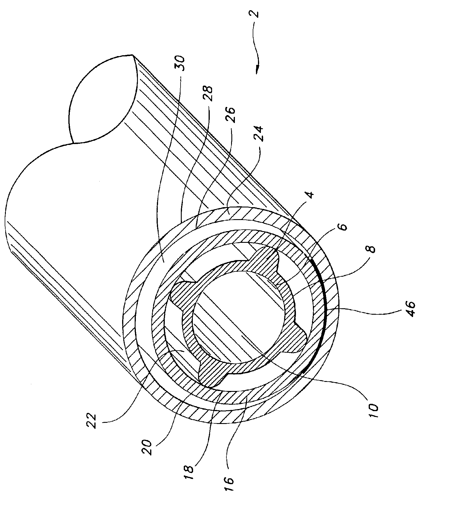
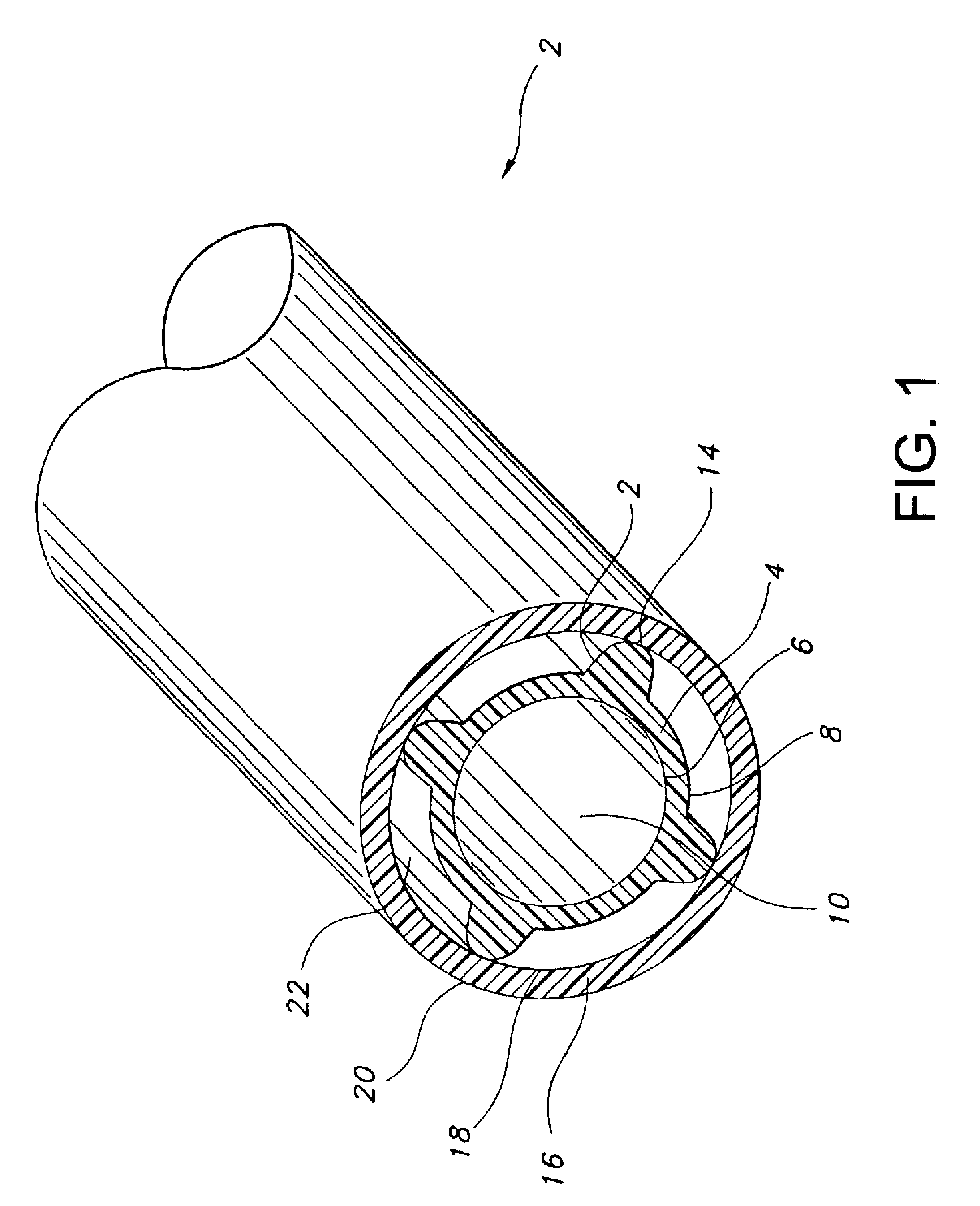
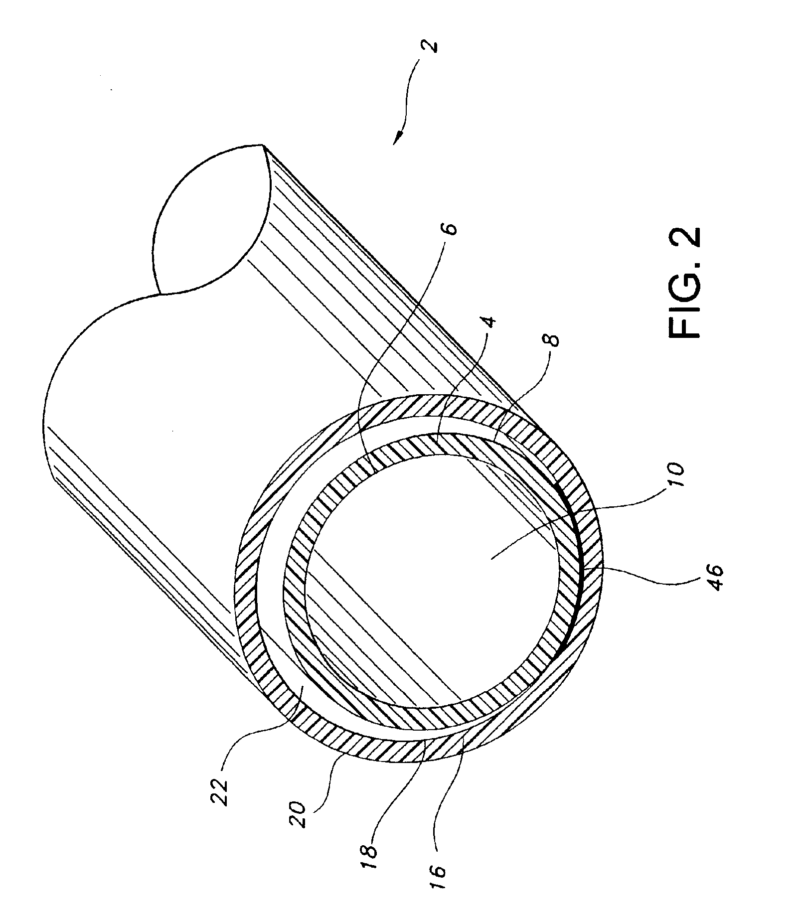
[0035]The prosthesis of the present invention includes an implantable self-sealing tubular structure having a plurality of secondary lumens between a primary and a secondary tubular structure. Desirably, the prosthesis is formed from extruded PTFE or other similar material which exhibits superior biocompatibility.

[0036]In the present invention, a primary tubular body is formed which defines a blood contacting lumen. A secondary tubular structure is formed about and integral with the first tubular structure at an outer wall of the primary tubular body. A portion of an inner wall of the secondary tubular body and a portion of an outer wall of the primary tubular body defines at least one secondary lumen between the tubular bodies. The secondary lumen may contain a non-biodegradable self-sealing elastomeric material. Optionally, a pharmacologically or physiologically active agent may be supplied in the graft for delivery to the patient.

[0037]In an advantageous aspect of the invention, ...


PUM

PropertyMeasurementUnit
internodal distanceaaaaaaaaaa

Abstract

The present invention provides an implantable graft, including a primary tubular body having a first outer wall surface and a first inner wall surface defining a primary blood contacting lumen, and a secondary tubular body having a second outer wall surface and a second inner wall surface. The secondary tubular body is located about the primary tubular body to form a space therebetween. The primary and secondary tubular bodies are joined by at least one rib.

Description

FIELD OF THE INVENTION[0001]The present invention relates generally to an implantable prosthesis. More particularly, the present invention relates to an implantable graft having an integral multi-lumen structure.BACKGROUND OF THE INVENTION[0002]Implantable grafts are commonly used in treatment of diseased blood vessels. One such device is a synthetic vascular graft designed to replace damaged or dysfunctional tissue. Such damage or dysfunction can arise, for example, from arterial or venous pathways that have been damaged by thrombosis, an aneurysm or occlusion. The graft provides an artificial lumen through which blood may flow.[0003]Natural blood vessels are often damaged during treatment of renal failure. For example, when treating patients with renal failure using dialysis, it is necessary to have ready access to blood vessels in order to continuously withdraw blood from the patient in amounts of over 200 ml / min. For dialysis to be effective, it must be repeated on a regular sch...

Claims


Application Information

Patent Timeline
Patent Type & Authority Patents(United States)
IPC IPC(8): A61F2/06A61L27/50A61L27/16A61L27/00A61L27/34
CPCA61F2/06A61L27/16A61L27/34A61L27/507C08L27/18
Inventor HENDERSON, JAMIE S.
Owner MAQUET CARDIOVASCULAR LLC
Why Eureka
Try Eureka