Object recognition apparatus for vehicle, and inter-vehicle distance control unit

a technology of object recognition and vehicle, applied in the field of vehicles, can solve the problems of difficult adjustment operation, inability to discriminate accurately between a non-vehicle and a vehicle, and the region in which a reflecting object exists, etc., and achieve the effect of accurately selecting an object and sufficient toleran

Inactive Publication Date: 2005-08-09
DENSO CORP
View PDF21 Cites 40 Cited by
  • Summary
  • Abstract
  • Description
  • Claims
  • Application Information

AI Technical Summary

Benefits of technology

[0012]The present invention has been developed with a view to eliminating the above-mentioned problems, and it is therefore an object of the present invention to provide a vehicle object recognition apparatus capable of outputting transmission waves throughout an appropriate angular range while allowing for a sufficient tolerance when a radar unit is mounted on a vehicle, and further to provide an inter-vehicle distance control unit capable of accurately selecting an object for the inter-vehicle distance control.

Problems solved by technology

In other words, if a transmission wave output axis is shifted depending on the mounted state of the radar unit, difficulty is encountered in making the discrimination between a non-vehicle and a vehicle, for that a region in which a reflecting object exists cannot be discriminated with accuracy.
However, the adjustment operation becomes more difficult as the tolerance (tolerable range) of the mounting angle of the radar unit is made smaller (narrower), and it takes time, which leads to an increase in manufacturing cost.
However, if this one's-lane probability map is applied to both a stopping (stationary) object and a moving object recognized through a forward obstacle recognition processing, the following problems arise.
However, in a case in which an obstacle recognized through the forward obstacle recognition processing is a moving object, even if it exists outside its own lane, there is a possibility that the moving object cuts into the lane immediately before oneself.
Thus, since the conventional one's-lane probability map is used for both the stopping object and moving object recognized through the forward obstacle recognition processing, the probability is not set in conjunction with a state of the object, which makes it difficult to precisely select an object for the inter-vehicle distance control.

Method used


Image

  • Object recognition apparatus for vehicle, and inter-vehicle distance control unit
  • Object recognition apparatus for vehicle, and inter-vehicle distance control unit
  • Object recognition apparatus for vehicle, and inter-vehicle distance control unit

Examples


first embodiment

(First Embodiment)

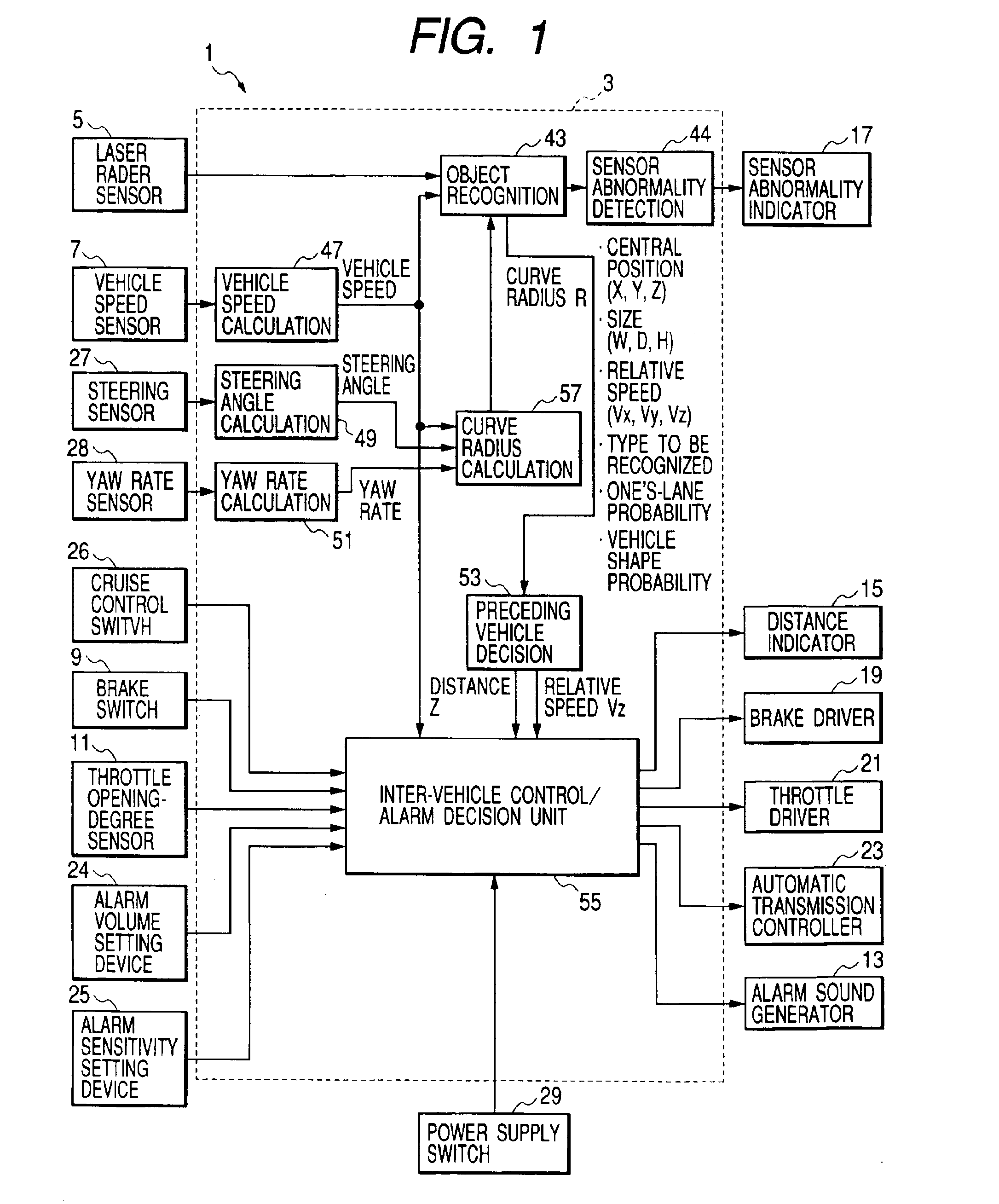
[0074]First of all, referring to the drawings, a description will be given hereinbelow of a vehicle control apparatus using an object recognition apparatus according to the present invention. This vehicle control apparatus is mounted in a vehicle and is designed to output an alarm when an obstacle exists in an alarming region or to control the vehicle speed according to a vehicle existing in a forward direction (preceding vehicle).

[0075]FIG. 1 is a flow diagram showing a system configuration of the vehicle control apparatus generally designated at reference numeral 1. The vehicle control apparatus 1 is constructed using a recognition / inter-vehicle control ECU 3 serving as a principal unit. The recognition / inter-vehicle control ECU 3 is basically composed of a microcomputer, and is equipped with input / output interfaces (I / O) and various types of drive circuits and various types of detection circuits. This hardware configuration is of a general type, and the descript...

second embodiment

(Second Embodiment)

[0172]Referring to the drawings, a description will be given hereinbelow of an inter-vehicle distance control unit according to a second embodiment of the present invention. This control unit is mounted on a vehicle and is designed to keep a predetermined inter-vehicle distance when capturing a preceding vehicle during constant-speed travel control.

[0173]FIG. 16 is an illustration of the entire configuration of an inter-vehicle distance control unit according to the second embodiment. In FIG. 16, the inter-vehicle distance control unit, generally designated at reference numeral 102, is made up of, in addition to a computer 104 which functions as a principal component, a scanning measurement device 106, a steering sensor 108, a yaw rate sensor 109, a vehicle speed sensor 110, a cruise control switch 112, an indicator 114, an automatic transmission controller 116, a brake switch 118, a brake driver 119, a throttle opening degree sensor 120 and a throttle driver 121....


PUM


Abstract

In an object recognition apparatus using a radar unit for a vehicle, in mounting the radar unit on the vehicle, a transmission wave is outputted throughout an appropriate angular range in a forward direction of the vehicle in a state where a margin is given to a tolerance of the mounting angle of the radar unit on the vehicle. Laser beams are radiated at a target placed at a predetermined positional relationship relative to the radar unit mounted on the vehicle to extract a laser beam which provides the maximum light-reception intensity in each of the X-axis and Y-axis directions. Moreover, a predetermined angular range is set in each of the X-axis and Y-axis directions so that the laser beam which provides the maximum light-reception intensity is centered therein, and the predetermined angular range is used as a recognition area.

Description

BACKGROUND OF THE INVENTION[0001]1) Field of the Invention[0002]The present invention relates to a vehicle object recognition apparatus which is designed to emit or radiate transmission waves throughout a predetermined angular range in each of vertical (vehicle-height) and horizontal (vehicle-width, lateral) directions from one vehicle to recognize an object in front of the vehicle on the basis of reflected waves thereof, and further to an inter-vehicle control unit.[0003]2) Description of the Related Art[0004]So far, for example, as disclosed in Japanese Patent Laid-Open No. 2002-40139, there has been proposed an object recognition apparatus designed to emit an optical wave or millimetric wave to detect a reflected wave thereof for recognizing an object existing in a forward direction. For example, such an apparatus is applicable to an apparatus made to detect a vehicle in a forward direction and issue an alarm, an apparatus made to control a vehicle speed for keeping a predetermin...

Claims


Application Information

Patent Timeline
Patent Type & Authority Patents(United States)
IPC IPC(8): B60K31/00B60K31/18G01S13/93G01S13/00G01S17/93G01S17/00G01S17/42G01S7/48G01S7/497G05D1/02G01S7/40G08G1/16G01S17/931G01S13/931
CPCB60K31/0008B60K31/185G01S7/4026G01S7/4972G01S13/931G01S17/42G01S17/936G05D1/0257G08G1/16B60W2420/00B60W2420/52B60W2520/14B60W2550/143G05D2201/0213G01S2007/4091G01S2007/4034G01S2007/403G01S2013/9321G01S2013/9325G01S2013/9339G01S2013/9346G01S2013/935G01S2013/9353G01S2013/9375G01S2013/9389G08G1/165G08G1/166G01S2013/9329G01S2013/9319G01S2013/93275G01S2013/93185G01S2013/932G01S2013/93271G01S17/931B60W2552/20B60W2552/30B60W2540/18G01S7/4034G01S7/403G01S7/4091
Inventor SAMUKAWA, YOSHIEMATSUOKA, KEIJINOZAWA, TOYOHITOOHKATA, HIROSHI
Owner DENSO CORP
Why Eureka
Try Eureka