
Reconfigurable image surface holograms

a holographic and image surface technology, applied in the field of computed holographic stereograms, to achieve the effect of reducing artifacts and minimizing or eliminating such artifacts

Inactive Publication Date: 2005-08-09
MASSACHUSETTS INST OF TECH
View PDF7 Cites 53 Cited by
  • Summary
  • Abstract
  • Description
  • Claims
  • Application Information

AI Technical Summary

Benefits of technology

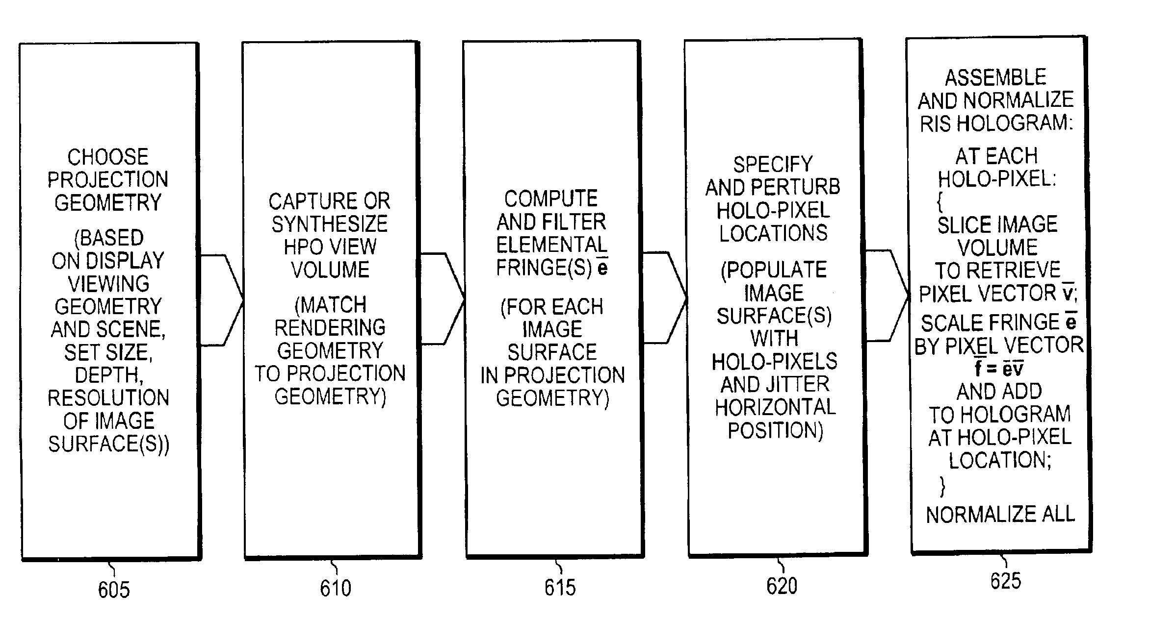
[0007]In the methods and systems of the reconfigurable image surface holograms of the present invention, many parameters and their effects, as represented by viewable images, are adjustable. In particular, as is explained in detail below, an image surface is spatially distinct from the hologram surface of the computed holographic stereograms, according to the principles of the invention. In addition, a plurality of image surfaces, at least one of which is distinct from the hologram surface, can be employed, according to principles of the invention. The viewable holographic stereograms are reconfigurable as a consequence of the selection of the number and position of image surfaces. In addition, some of the image characteristics of the holographic stereograms can be controlled and optimized. For example, some artifacts that appear in holographic stereograms of the prior art are due in part to errors in focus or bandlimiting relating to the distance of a portion of the scene from the image surface. With a plurality of adjustable image planes, one can select positions that minimize or eliminate such artifacts. In addition, by relaxing the requirement that the elements of the holographic stereogram are abutting, the systems and methods of the invention provide a mechanism for reducing artifacts caused by abrupt changes in adjacent elements of the holographic stereo gram.
[0009]Second, the location, size, and resolution of the image plane are variable. As implied above, this flexibility allows one or more image planes (the plane of highest spatial reconstruction accuracy) to be positioned anywhere in the image volume, so long as an image plane is spatially distinct from the hologram plane. The design also permits the image plane's size and holopixel resolution to be adjusted for a given three-dimensional scene. Again, other existing stereogram computation and electronic display techniques use a fixed image plane depth and resolution. Third, scene parallax resolution is also variable. Like other stereogram techniques, this approach reconstructs a three-dimensional scene using a series of rendered or otherwise captured two-dimensional parallax views. Unlike other stereogram techniques, the computation of holograms in accordance herewith does not require that a given parallax sweep contain a fixed number of views, but rather allows the number of views to be adjusted for optimal reconstruction. For instance, one might employ relatively few parallax views for a shallow scene, and substantially more views to reconstruct a deep scene without aliasing artifacts.
[0010]Fourth, instances of the precomputed diffractive pattern used to reconstruct holopixels in an image plane are prefiltered and then overlapped on the hologram, to eliminate diffraction artifacts in reconstruction. The precomputed pattern may be modeled in a variety of ways to adjust the image and projection characteristics of each reconstructed holopixel.
[0011]Fifth, the hologram format of the present invention permits the display of one or multiple image surfaces. A given electro-holographic display architecture can mimic a volumetric display, a stereographic display, or an interesting hybrid of the two. This format provides a rich testbed for, e.g., comparing these different display types and their underlying representation and reconstruction of light fields.

Problems solved by technology

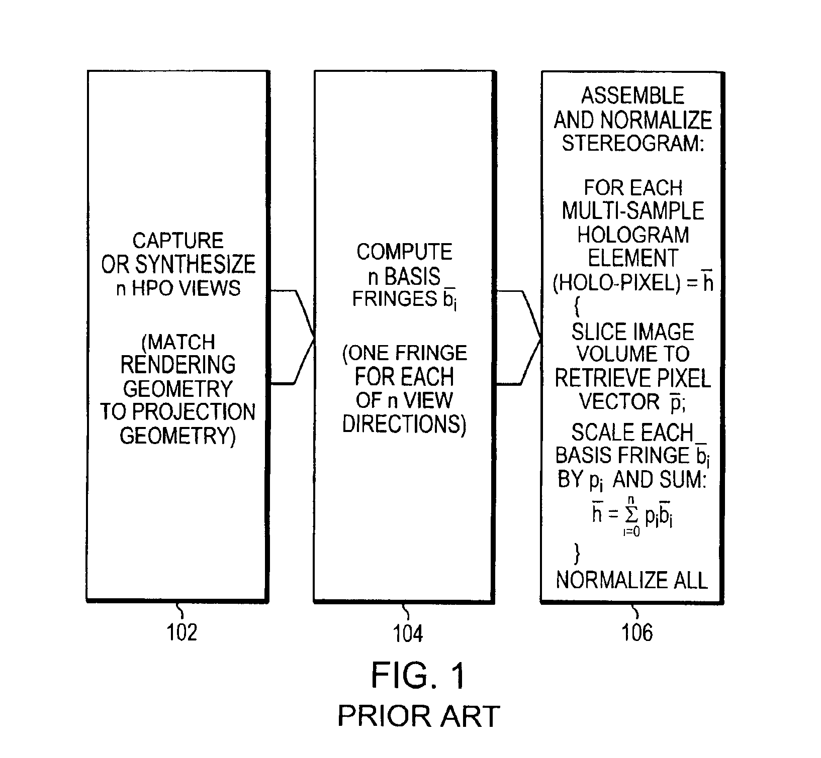
For example, some artifacts that appear in holographic stereograms of the prior art are due in part to errors in focus or bandlimiting relating to the distance of a portion of the scene from the image surface.

Method used


Image

  • Reconfigurable image surface holograms
  • Reconfigurable image surface holograms
  • Reconfigurable image surface holograms

Examples


Embodiment Construction

[0041]The systems and methods of the invention will be described first in high level overview, in order to familiarize the reader with the features of the invention. Thereafter, the systems and methods will be described in greater technical detail. Some of the advantages and illustrative examples of the systems and methods of the invention will then be given.

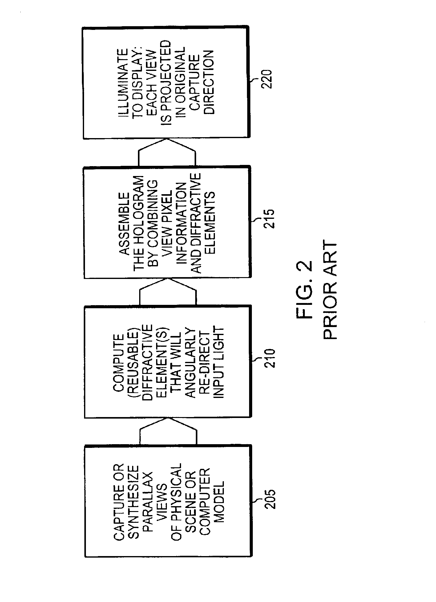
[0042]FIG. 2 depicts in generalized form the process of computing and displaying a conventional holographic stereogram. In one embodiment, the systems and methods of the invention involve the operations shown in FIG. 2, each of which may involve discrete steps. A first operation is the capture (or synthesis) of a plurality of two-dimensional images of a three-dimensional object or scene, more generally a three-dimensional target, which is to be depicted holographically, as indicated in box 205. A second operation is the computation of diffractive elemental fringes that angularly redirect input light, as indicated in box 210. A t...


PUM


Abstract

The invention provides systems and methods for generating and displaying computational holographic stereograms having a hologram surface and a spatially distinct image surface. A three-dimensional object or scene is captured or synthesized as a stack of views. The holographic stereogram is computed by obtaining a diffractive fringe vector e and a pixel slice v through the stack of views, and generating the holopixel representation f=ev. The holographic stereogram is displayed using one or more image surfaces that are spatially distinct from the hologram surface. the surfaces can be any two-dimensional structures defined on a three-dimensional space, including, but not limited to planar, cylindrical, spherical, or other surfaces. The holographic stereograms are adjustable through variations in an image surface depth, an image surface resolution, a number of image surfaces, and a scene parallax resolution.

Description

FIELD OF THE INVENTION[0001]This invention relates generally to computed holographic stereograms. More particularly, the invention relates to computed holographic stereograms having an image surface that is spatially distinct from the surface on which the holographic stereogram is written or recorded.BACKGROUND OF THE INVENTION[0002]Holography is a display technology in which a viewer sees a scene that varies as the angle at which the viewer views the scene changes. An example of a conventional hologram that is now in common use is the small image that is often imbedded in the front surface of a credit card. In that usage, the hologram is provided as a security or anti-counterfeiting, device, because of the difficulty involved in producing a hologram.[0003]A great deal of information is required to describe a visually complicated three-dimensional scene over a reasonable angle of view. In practical holography systems, one has only a limited amount of hologram bandwidth in which to e...

Claims


Application Information

Patent Timeline
IPC IPC(8): G03H1/26G03H1/08
CPCG03H1/0808G03H1/268G03H2001/043G03H2210/454G03H2210/441Y10S359/90
Inventor PLESNIAK, WENDY J.HALLE, MICHAEL W.
Owner MASSACHUSETTS INST OF TECH
Learn More