Waste heat collecting system having rankine cycle and heating cycle

a technology of waste heat collection and rankine cycle, which is applied in the direction of machines/engines, transportation and packaging, light and heating apparatus, etc., can solve the problems of difficulty in practicing the invention of the above prior art, and achieve the effect of suppressing the temperature of the thermal engine, reducing the fuel consumption ratio of the engine, and increasing the friction resistan

Inactive Publication Date: 2005-08-16
DENSO CORP +1
View PDF7 Cites 38 Cited by
  • Summary
  • Abstract
  • Description
  • Claims
  • Application Information

AI Technical Summary

Benefits of technology

[0009]According to this feature of the invention, a kinetic energy can be obtained from the waste heat from the thermal engine, without causing a decrease of a fuel consumption ratio for the engine, because an increase of friction resistance (friction loss) due to a decrease of a temperature of the thermal engine can be suppressed.
[0014]Accordingly, a kinetic energy can be obtained from the waste heat from the thermal engine, without causing a decrease of a fuel consumption ratio for the engine, because an increase of friction resistance (friction loss) due to a decrease of a temperature of the thermal engine can be suppressed. And in addition, the refrigerating cycle can be operated.

Problems solved by technology

Furthermore, it may be difficult to practically carry out the invention of the above prior art (JP S63-96449), because it is not fully disclosed how the refrigerating cycle and the Rankine cycle are switched over from one to the other and how the Rankine cycle is performed.

Method used


Image

  • Waste heat collecting system having rankine cycle and heating cycle
  • Waste heat collecting system having rankine cycle and heating cycle
  • Waste heat collecting system having rankine cycle and heating cycle

Examples


first embodiment

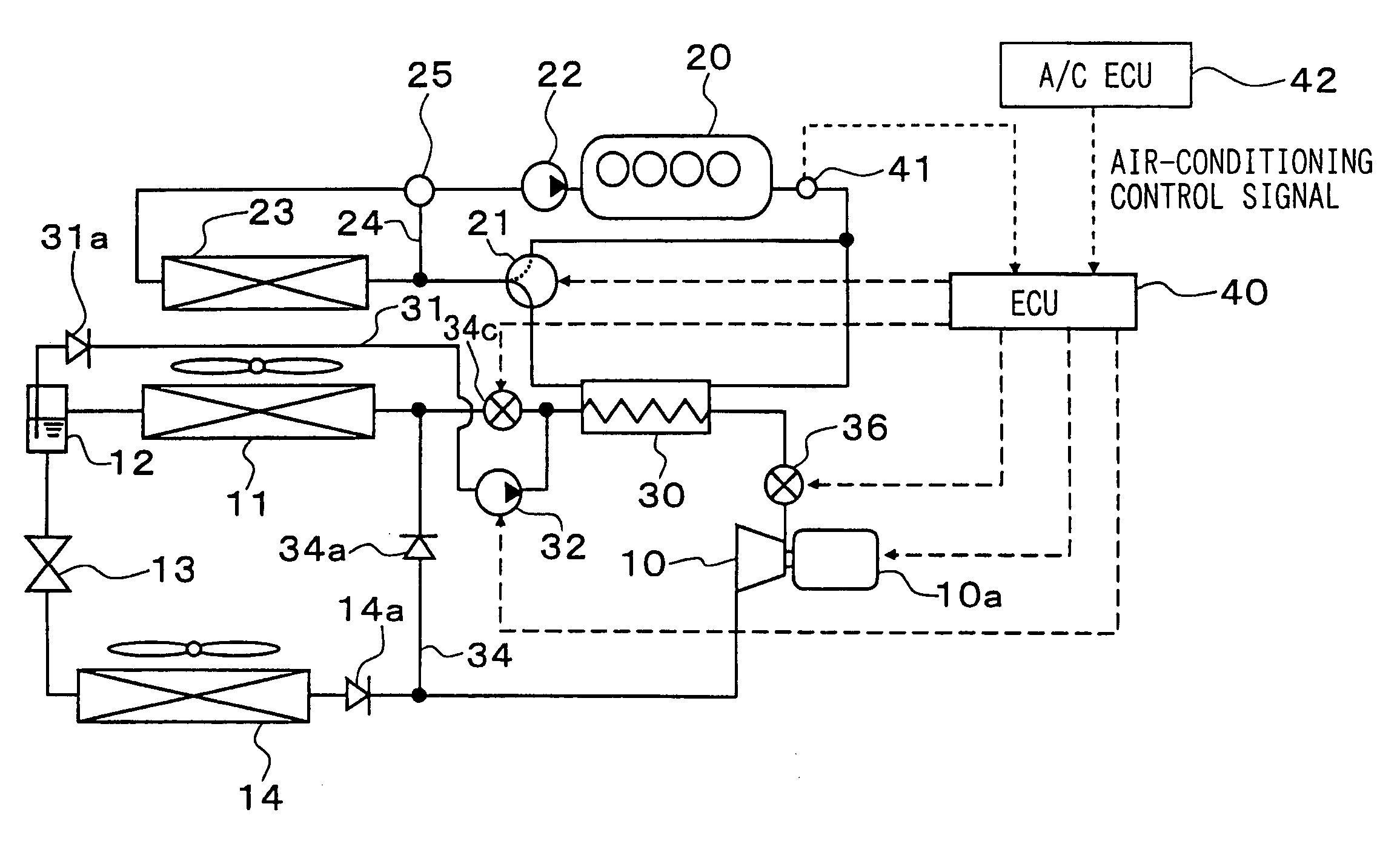
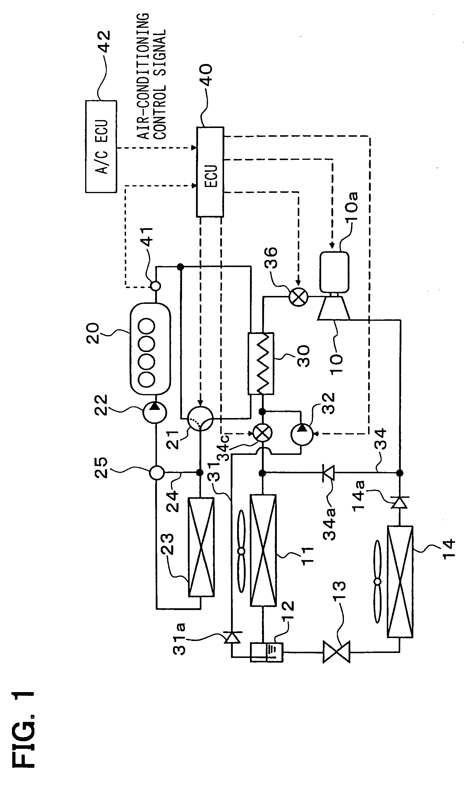
[0022]FIG. 1 is a schematic diagram showing a vapor compression type refrigerating apparatus according to a first embodiment of the present invention, in which a refrigerating cycle having a rankine cycle is used for an air-conditioning apparatus for a motor vehicle.

[0023]The vapor compression type refrigerating apparatus having the rankine cycle collects an energy from a waste heat form an internal combustion engine for generating a driving force for a vehicle, wherein the internal combustion engine is operating as a thermal engine. The refrigerating apparatus makes use of thermal energy generated thereat for performing an air-conditioning operation for the vehicle.

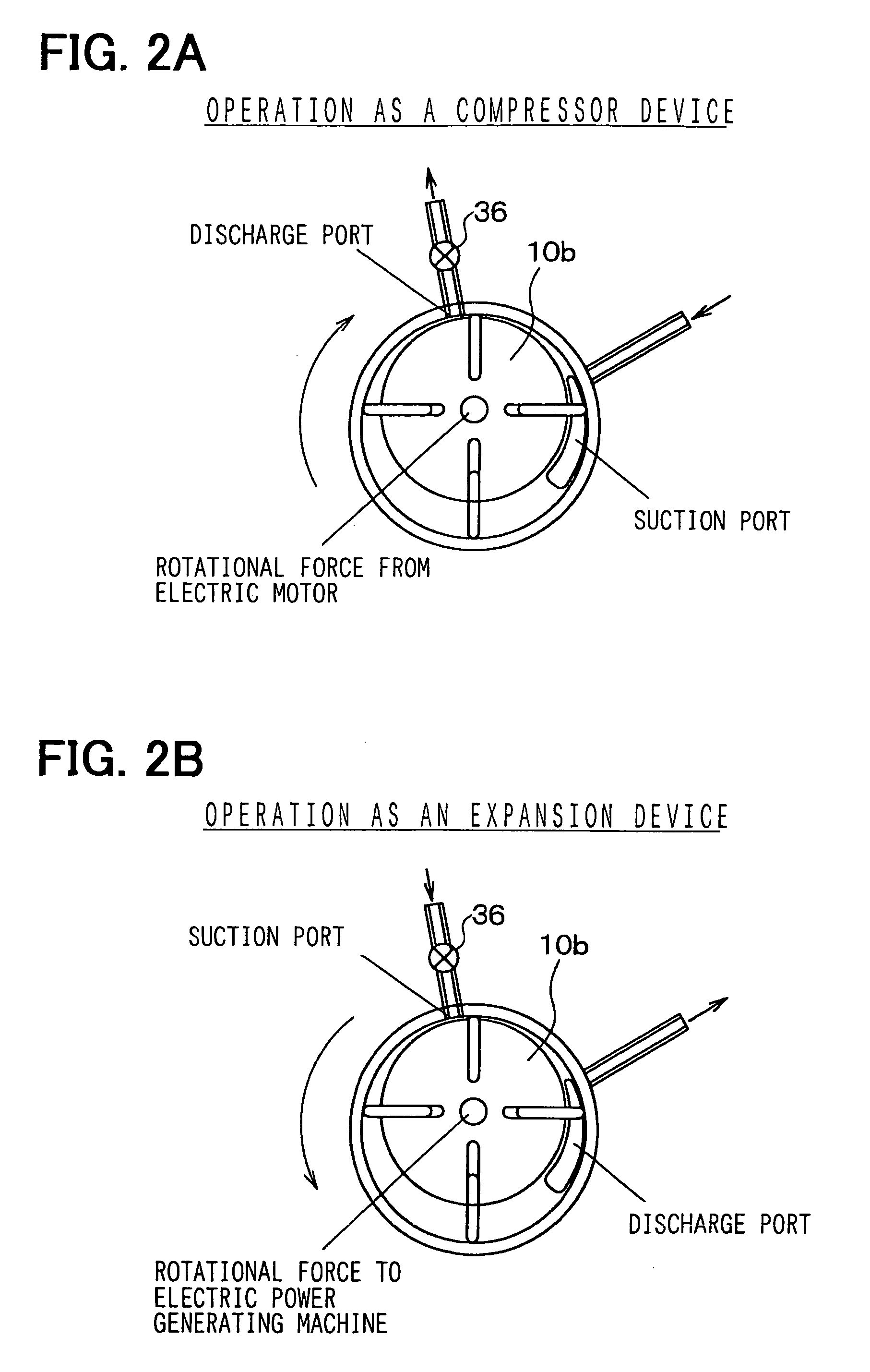
[0024]In FIG. 1, a compressor device 10 integrally formed with an expansion device is a fluid machine having a function of a compressor for compressing a refrigerant and a function of an expander for generating a driving force by expanding a superheated vapor in an isenthropic manner.

[0025]A reference numeral 10a designa...

second embodiment

[0069]In the above first embodiment, the fluid machine 10 comprises the compressor device integrally formed with the expansion device. In FIG. 5 showing a second embodiment, however, a compressor device 33a and an expansion device 33b are independently provided, wherein the compressor device 33a and the expansion device 33b are operatively connected with each other by a one-way clutch (not shown).

[0070]Control valves 34a and 34b are respectively connected to the compressor device 33a and the expansion device 33b, an opening and closing of which is controlled by the ECU 40. The control valve 34a is opened and the control valve 34b is closed for the air-conditioning operation, while the control valve 34a is closed and the control valve 34b is opened for the waste heat collecting operation.

third embodiment

[0071]In the above first embodiment, the three way valve 21 is changed over so that the engine cooling water may flow from the engine 20 through the heating device 30, during the waste heat collecting operation mode. The operation of the waste heat collection can be, however, modified in the following manner. The engine cooling water is kept flowing through the heating device 30, and the water pump 22 and / or the liquid pump 32 is controlled by the ECU 40 depending on the temperature of the engine cooling water, so that the waste heat collecting operation is performed when the temperature Tw of the waste heat exceeds a predetermined value.

Other Embodiments

[0072]The present invention shall not be limited to the embodiments described above and many other modifications can be possible.

[0073]For example, the kinetic energy generated at the expansion device can be stored as an energy of movement in a flywheel or as an elastic potential energy in a spring.

[0074]Other types of the fluid mac...


PUM


Abstract

An object of the invention is to provide a rankine cycle suitable for a use for a motor vehicle. In a waste heat collecting system having the rankine cycle and a refrigerating cycle, when ECU receives an air-conditioning signal from A / C ECU, the refrigerating cycle is operated, by preceding the operation of the rankine cycle. In the case that there is no air-conditioning signal and a temperature of an engine cooling water is higher than a predetermined value, the rankine cycle is operated.

Description

CROSS REFERENCE TO RELATED APPLICATION[0001]This application is based on Japanese Patent Application No. 2003-390893 filed on Nov. 20, 2003, the disclosures of which is incorporated herein by reference.FIELD OF THE INVENTION[0002]The present invention relates to a waste heat collecting system having a Rankine cycle for collecting heat energy from a thermal engine, in particular to a vapor compression type refrigerating apparatus (an air-conditioning apparatus) for a motor vehicle, wherein an internal combustion engine is used as the thermal engine.BACKGROUND OF THE INVENTION[0003]A Rankine cycle comprises a vapor generating device for generating a super heated vapor by heating a liquid-phase fluid, an expansion device for generating a kinetic energy by expanding the super heated vapor in an isenthropic manner, a condenser for liquidizing the vapor expanded at the expansion device, a liquid pump for supplying a liquid-phase fluid to the vapor generating device, and so on, as disclose...

Claims


Application Information

Patent Timeline
Patent Type & Authority Patents(United States)
IPC IPC(8): F01K23/06F01K23/10B60H1/00B60H1/32F25B1/00
CPCB60H1/00878B60H1/00899F01K23/065B60H2001/00928B60H2001/00949B60H2001/3295B60H2001/3297Y02T10/16Y02T10/166Y02T10/12
Inventor INABA, ATSUSHIHAMADA, SHINICHIHISANAGA, SHIGERUHOTTA, TADASHI
Owner DENSO CORP
Why Eureka
Try Eureka