Apparatus and method for forming silica glass elements

Inactive Publication Date: 2005-08-16
TOSHIBA MASCH CO LTD
View PDF14 Cites 5 Cited by
  • Summary
  • Abstract
  • Description
  • Claims
  • Application Information

AI Technical Summary

Benefits of technology

[0010]It is an object of the invention to shorten the heating and pressing time during the forming, b

Problems solved by technology

In addition, there arises a problem that large amounts of glass grinding dust harmful to workers are generated.
Moreover, the former method has another problem that it is difficult to manufacture high-value added glass elements having optical surfaces of aspherical surface shape with the same accuracy and in large quantities.
However, when silica glass elements are formed by the above-described manufacturing met

Method used


Image

  • Apparatus and method for forming silica glass elements
  • Apparatus and method for forming silica glass elements
  • Apparatus and method for forming silica glass elements

Examples


Embodiment Construction

[0029]An embodiment of the invention will be described below by referring to the drawings.

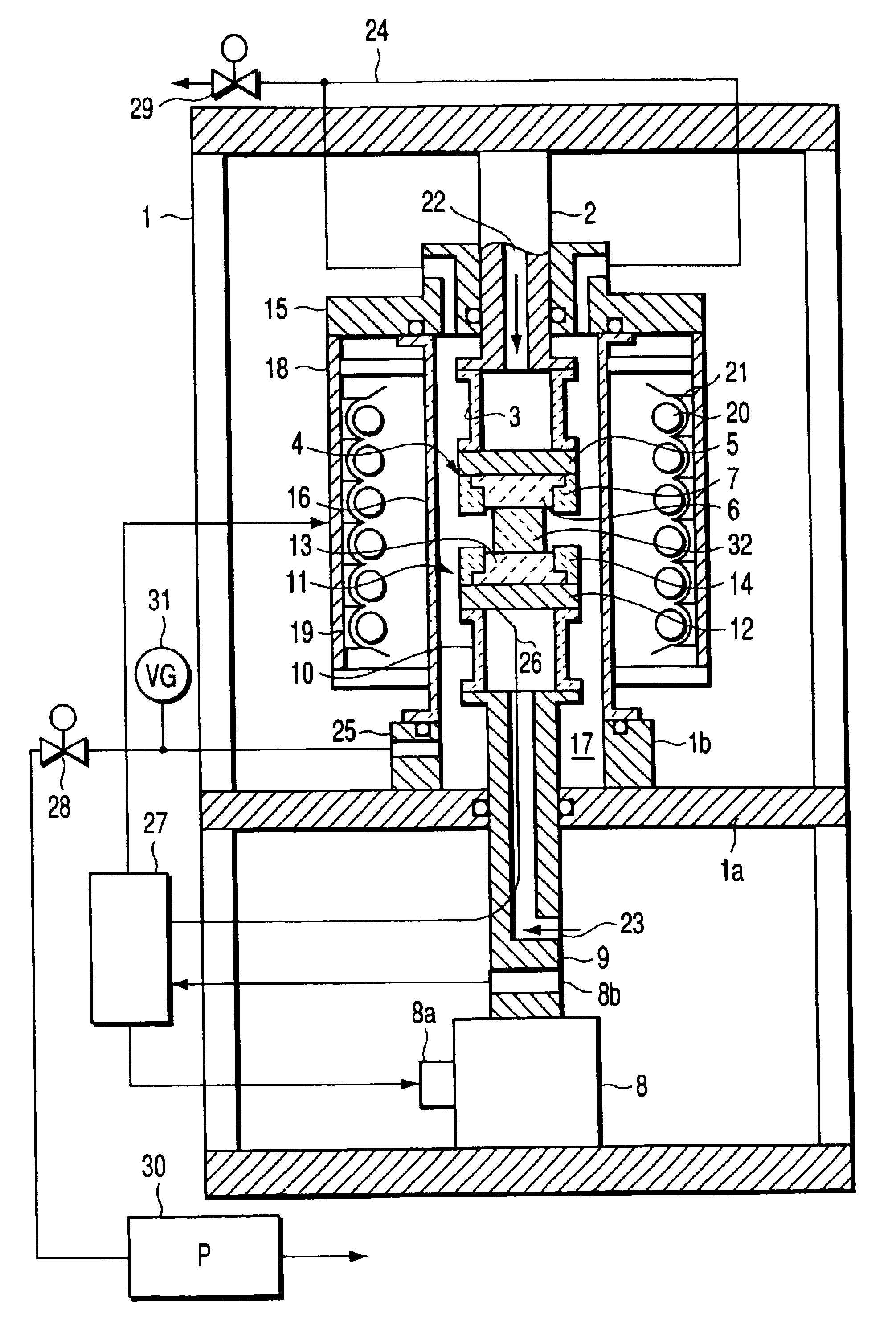
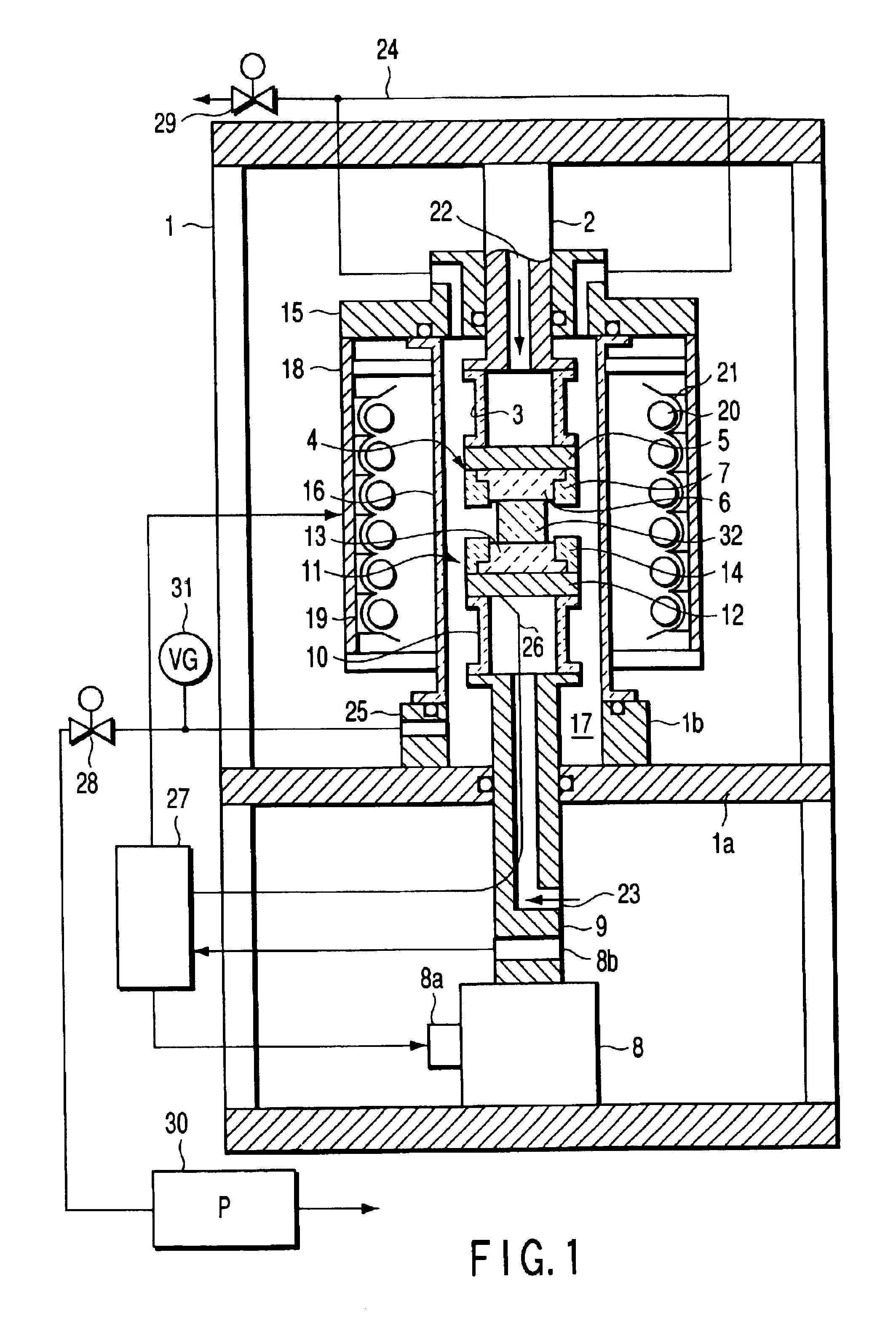
[0030]An example of an apparatus for forming a silica glass element related to the invention is shown in FIG. 1 (a general view) and FIG. 2 (a partial enlarged view). In this apparatus, a fixed shaft 2 extends downward from the upper part of a frame 1 and at the bottom end of the fixed shaft 2 is attached a top die assembly 4 by a bolt, etc. (not shown) through a heat insulating cylinder 3 made of ceramics. The top die assembly 4 comprises a top die plate 5 made of metal or ceramic carbon, a top core mold 6 for forming a figure of a silica glass element to be formed and made of vitrified carbon and a top mold die 7 surrounding a periphery of the top core mold and made of isotropic carbon. The top mold die 7 and top core mold 6 are attached to top die plate 5, and the top die plate 5 is attached to a heat insulating cylinder 3.

[0031]A drive unit 8, such as a screw jack, which uses a servomotor 8...


PUM

PropertyMeasurementUnit
Temperatureaaaaaaaaaa
Forceaaaaaaaaaa
Torqueaaaaaaaaaa

Abstract

The forming apparatus has top and bottom die assemblies which form a heated silica glass material by press forming. These top and bottom die assemblies include, respectively, mold dies, which are made of isotropic carbon, and core molds, which are made of vitrified carbon. The heating and pressing time of a silica glass element, which requires a high forming temperature, is shortened by pinching the silica glass material between top and bottom core molds by controlling a torque so as to produce a close contact condition which permits heat transfer from the top and bottom core molds to the silica glass material between the top and bottom core molds.

Description

CROSS-REFERENCE TO RELATED APPLICATIONS[0001]This application is based upon and claims the benefit of priority from the prior Japanese Patent Application No. 2001-298087, filed Sep. 27, 2001, the entire contents of which are incorporated herein by reference.BACKGROUND OF THE INVENTION[0002]1. Field of the Invention[0003]The present invention relates to an apparatus and a method for forming silica glass elements in which the shortening of the heating time of a glass material for forming is particularly aimed at.[0004]2. Description of the Related Art[0005]Methods for manufacturing glass elements such as glass lenses that are required to provide high accuracy are broadly divided into two: a method which involves forming optical surfaces by grinding and polishing a glass material and a method by reheat pressing. Glass elements are often manufactured by the former method.[0006]In the former method, however, a dozen or so steps are required for forming curved surfaces by grinding and pol...

Claims


Application Information

Patent Timeline
IPC IPC(8): C03B11/00C03B11/06C03B11/12C03B11/08
CPCC03B11/005C03B11/08C03B11/084C03B11/086C03B11/088C03B11/122C03B11/125C03B2215/07C03B2215/24C03B2215/44C03B2215/66C03B2215/72C03B2215/73C03B11/12
Inventor MURAKOSHI, HIROSHIMATSUMURA, SHUSAKU
Owner TOSHIBA MASCH CO LTD
Why Eureka
Try Eureka