Internal combustion engine with combustion heater

a combustion heater and combustion engine technology, which is applied in the direction of engine starters, combustion-air/fuel-air treatment, lighting and heating apparatus, etc., can solve the problems of insufficient purging of low temperature of combustion gas discharged from the combustion heater, and inability of catalyst converters to sufficiently purge exhaust gas of harmful gas components. , to achieve the effect of reducing the heat exchange rate between the combustion gas and the heating medium, reducing the quantity of heat transfer

Inactive Publication Date: 2005-08-16
TOYOTA JIDOSHA KK
View PDF11 Cites 5 Cited by
  • Summary
  • Abstract
  • Description
  • Claims
  • Application Information

AI Technical Summary

Benefits of technology

[0016]In the thus constructed internal combustion engine having the combustion heater, for example, as in the case where there arises a necessity of raising the temperature of the exhaust gas purifying device provided on the exhaust gas passageway of the internal combustion engine, the heat exchange rate decreasing means decreases the heat exchange rate in the heat exchange unit when there occurs a necessity of discharging the combustion gas holding comparatively much heat from the combustion heater. Namely, when there arises the necessity of discharging the combustion gas holding comparatively a large quantity of heat from the combustion heater, the heat exchange rate decreasing means decreases the quantity of heat transferred to the engine cooling water from the combustion gas.
[0037]Moreover, in the internal combustion engine having the combustion heater according to the present invention, the fan may be installed at a side end on an upstream side or on a downstream side in a flow direction of the combustion gas within the combustion heater. In short, the fan may be installed in such a portion that the fresh air can be forcibly introduced into the combustion chamber. In this case, the installing portion of the fan can be selected from the upstream-sided end and the downstream-sided end in the flow direction of the combustion gas, and it is therefore possible increase a degree of freedom of designing the combustion heater.

Problems solved by technology

In this type of catalyst converter is, however, when a temperature of the catalyst of this catalyst converter is uniformly equal to or higher than a predetermined activation temperature, the catalyst is activated, and harmful gas components contained in the exhaust gas can be purged of.
Therefore, the catalyst converter is incapable of sufficiently purging the exhaust gas of the harmful gas components when the catalyst temperature of the catalyst converter is lower than the activation temperature.
Further, in the case where the temperature of the engine cooling water is low as when the internal combustion engine is in the cold state, upon an execution of the heat exchange between the combustion gas and the engine cooling water, it follows that a comparatively large quantity of heat is transferred to the engine cooling water from the combustion gas, and there might be a possibility where the temperature of the combustion gas discharged from the combustion heater gets extremely low.
Therefore, even when introducing into the exhaust gas purifying device the combustion gas after undergoing the heat exchange with the engine cooling water in the combustion heater, it is difficult to promptly activate the catalyst converter.

Method used


Image

  • Internal combustion engine with combustion heater
  • Internal combustion engine with combustion heater
  • Internal combustion engine with combustion heater

Examples


applied example 1

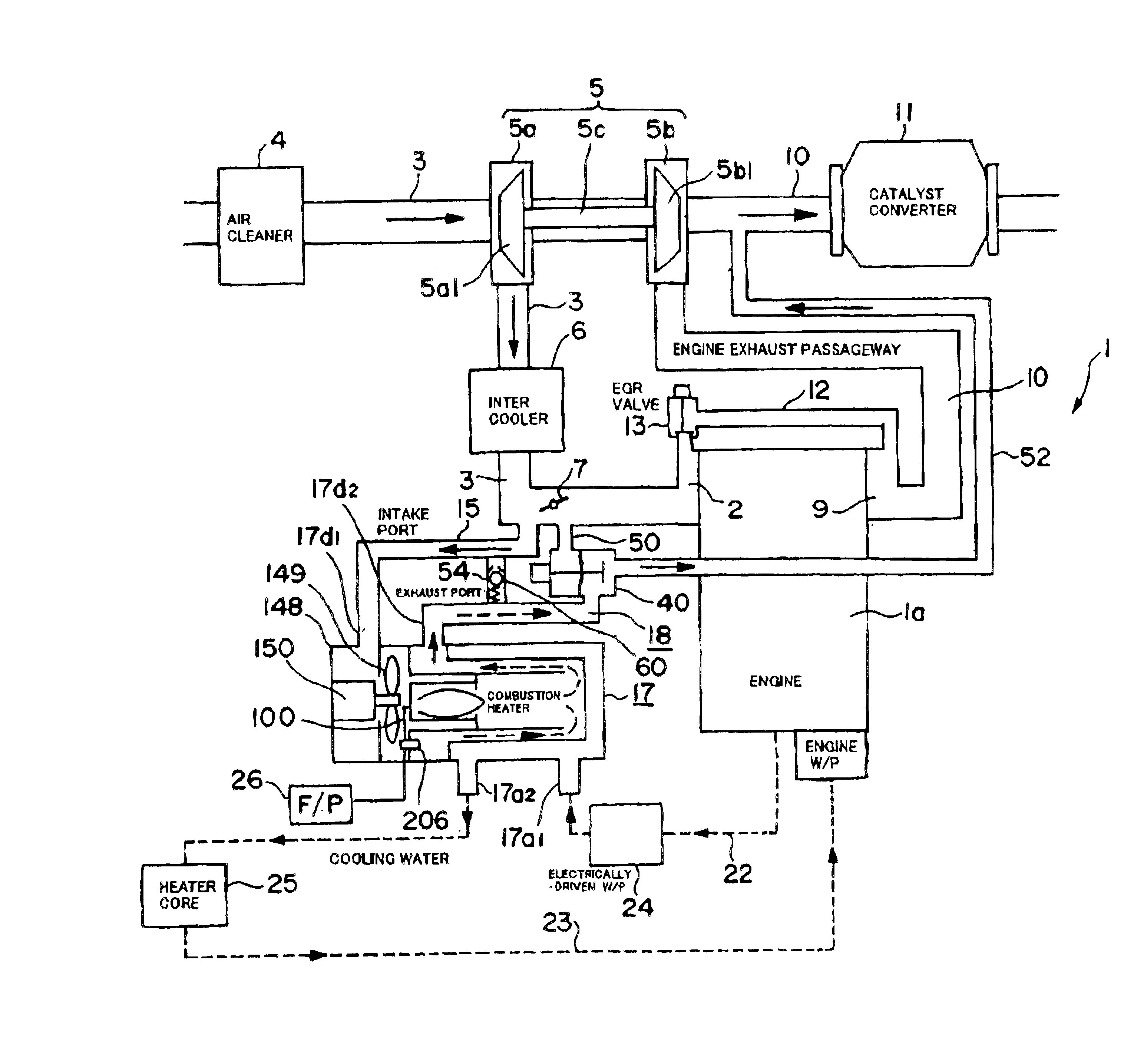
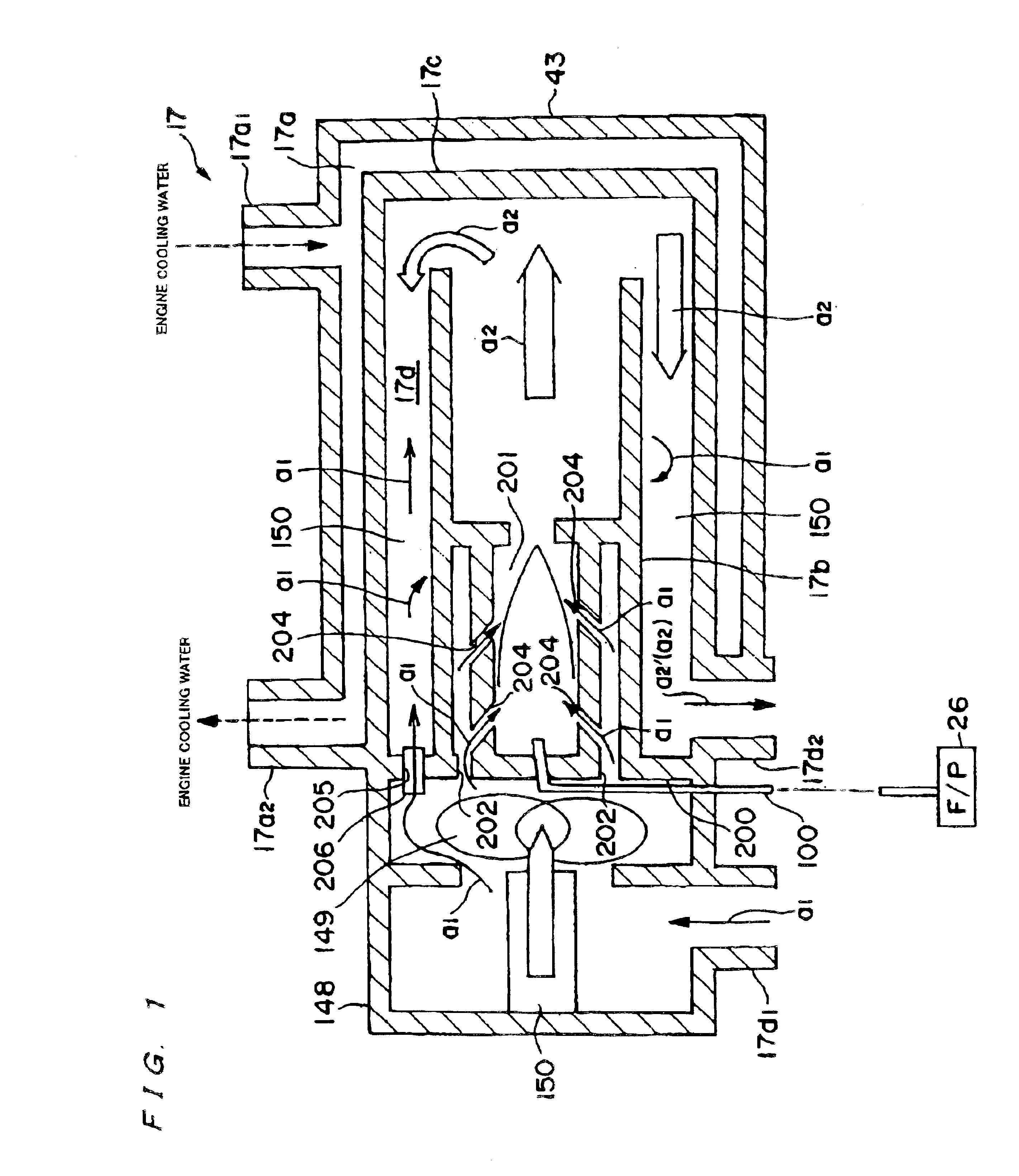
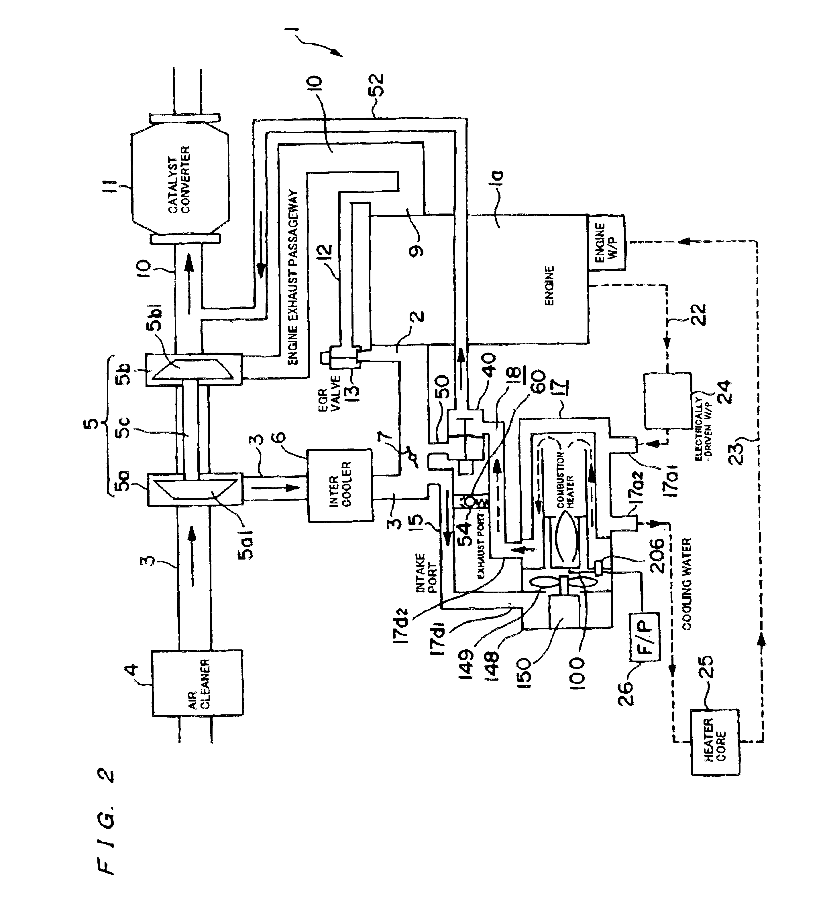
[0064]An applied example 1 will be explained with reference to FIGS. 1 and 2.

[0065]The internal combustion engine 1 is a lean combustion type multicylinder engine such as a diesel engine and so on, wherein an intake manifold 2 is connected to each of the unillustrated cylinders within the engine body 1a thereof. Respective branch pipes of the intake manifold 2 communicate via an unillustrated intake ports with the combustion chambers of the respective cylinders. The intake manifold 2 described above is connected to an intake pipe 3 as an intake passageway, and the intake pipe 3 is connected to an air cleaner containing an air filter.

[0066]A compressor housing 5a for a turbocharger 5 as a centrifugal supercharger is provided more downstream of the intake pipe 3 than the air cleaner 4. A compressor wheel 5a1 is rotatably supported within the compressor housing 5a. A rotary shaft of this compressor wheel is integrally connected to a rotary shaft of a turbine wheel 5b1 rotatably support...

applied example 2

[0103]Next, an applied example 2 will be described referring to FIG. 3.

[0104]A different point of this applied example 2 from the applied example 1 is a feasibility of being applied to an internal combustion engine including no turbocharger. The same effect as that of the applied example 1 can be acquired in this applied example 2.

APPLIED EXAMPLE 3

[0105]Next, an applied example 3 will be described referring to FIG. 4.

[0106]A different point of this applied example 3 from the applied example 2 is that the fresh air introduction pipe 15 opens to the atmospheric air, whereby the suction air is supplied directly from within the atmospheric air. The same effects as those of the applied examples 1 and 2 can be acquired in this applied example 3.

applied example 3

[0107]Next, an applied example 4 will be described referring to FIG. 5.

[0108]A different point of this applied example 4 from the applied example 3 is that the combustion gas discharge pipe 18 is connected not to the intake pipe 3 but only to the exhaust pipe 10, and that a known opening / closing valve 300 is provided as a substitute for the three-way valve 40.

[0109]The intake port of the combustion heater 17 opens to the atmospheric air so that the suction air is supplied directly from within the atmospheric air, however, it does not mean that the structure itself of the combustion heater 17 changes. Accordingly, the same effects as those of the applied examples 1, 2 and 3 can be acquired also in this applied example 4.


PUM


Abstract

The present invention aims at providing a technology capable of increasing a heat quantity of a combustion gas discharged from a combustion heater in an internal combustion engine having the combustion heater. To accomplish this object, the internal combustion engine having the combustion heater comprises a combustion chamber (17d) for combusting a fuel, an engine cooling water circulating between the combustion chamber (17d) and an engine-related element, a heat exchange unit (17a, 17c, 150) for performing a heat exchange between the engine cooling water and a combustion gas produced in the combustion chamber (17d), and heat exchange rate decreasing means (149, 205) for decreasing a heat exchange rate in said heat exchange unit (17a, 17c, 150).

Description

TECHNICAL FIELD[0001]The present invention relates to an internal combustion engine having a combustion heater.BACKGROUND ARTS[0002]In an internal combustion engine mounted in an automobile etc, particularly in a lean combustion type internal combustion engine that tends to have a small exothermic quantity as in a diesel engine, there is known a technology of providing a combustion heater together for the purpose of enhancing a performance of a heating device for a room and speeding up a warm-up of the internal combustion engine at a cold time.[0003]The combustion heater described above includes, for example, a combustion chamber independent of the internal combustion engine, a water passageway (which will hereinafter be called an [intra-heater cooling water passageway]) formed so as to surround this combustion chamber, an engine cooling water introduction pipe for leading the engine cooling water into the intra-heater cooling water passageway from a water jacket of the internal com...

Claims


Application Information

Patent Timeline
Patent Type & Authority Patents(United States)
IPC IPC(8): F01N3/20F01P3/20F02B37/16F02B37/12F02M31/06F02M31/16F02M31/02F02B37/00F02M25/07F01N3/24F02N19/04
CPCF01N3/2033F01P3/20F02B37/166F02M31/06F02M31/163F01P2037/02F01P2060/18F02B37/00F02M25/0707F23N2041/14Y02T10/144Y02T10/126Y02T10/26F02M26/05F23N2241/14Y02T10/12
Inventor SUZUKI, MAKOTO
Owner TOYOTA JIDOSHA KK
Why Eureka
Try Eureka