Autostereoscopic display

a display and autostereoscopic technology, applied in the field of autostereoscopic display, can solve the problems of headaches and other symptoms of visual strain, non-ideal view position, and difficulty in aligning a moveable element, so as to reduce the tolerancing requirements, reduce or avoid difficulties, and maximise the suppression of light from the barrier region in the visible spectrum

Active Publication Date: 2005-08-16
SHARP KK
View PDF5 Cites 30 Cited by
  • Summary
  • Abstract
  • Description
  • Claims
  • Application Information

AI Technical Summary

Benefits of technology

[0029]Where the parallax optic is embodied as a parallax barrier, the parallax barrier may comprise a first layer and a removable second layer, the first layer comprising barrier regions for passing light having a first polarisation and aperture regions for supplying at least light having a second polarisation which is substantially orthogonal to the first polarisation, the second layer comprising a polariser for passing light of the second polarisation. The second layer acts as an output polariser which absorbs light of the first polarisation and transmits light of the second polarisation when the display is in its 3D mode. The first layer may be fixed in correct registration with respect to the remainder of the autostereoscopic display. Switching between autostereoscopic and non-autostereoscopic modes can be achieved by removing and replacing the second layer, which requires only angular registration with respect to the rest of the display, thus reducing the tolerancing requirements so that difficulties with aligning a moveable element can be re

Problems solved by technology

Pseudoscopic images create problems because they often appear to have some depth despite the depth information being misleading or false.
Further, pseudoscopic viewing is known to cause headaches and other symptoms of visual strain.
This again leads to a non-ideal view position which is known to cause headaches and other symptoms of visual strain.
Such alignment is time-consuming and troublesome and therefore substantially

Method used


Image

  • Autostereoscopic display
  • Autostereoscopic display
  • Autostereoscopic display

Examples


Embodiment Construction

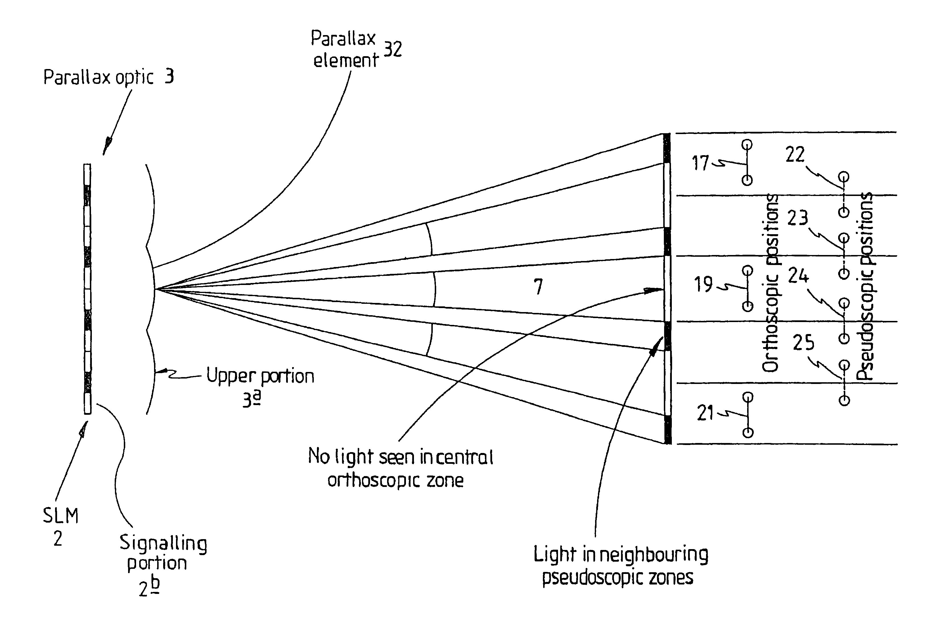
[0050]FIG. 5 illustrates the VPI part of an autostereoscopic display which differs from that shown in FIGS. 3 and 4 in that the pitch of the parallax elements 32 of the upper portion 3a of the parallax optic 3 is equal to one and a half times the pitch of the parallax elements 6 of the part of the parallax optic 3 which forms the viewing zones shown in FIG. 3. This contrasts with the pitch of the elements 32 in FIG. 4, which is twice that of the pitch of the elements 6 in FIG. 3.

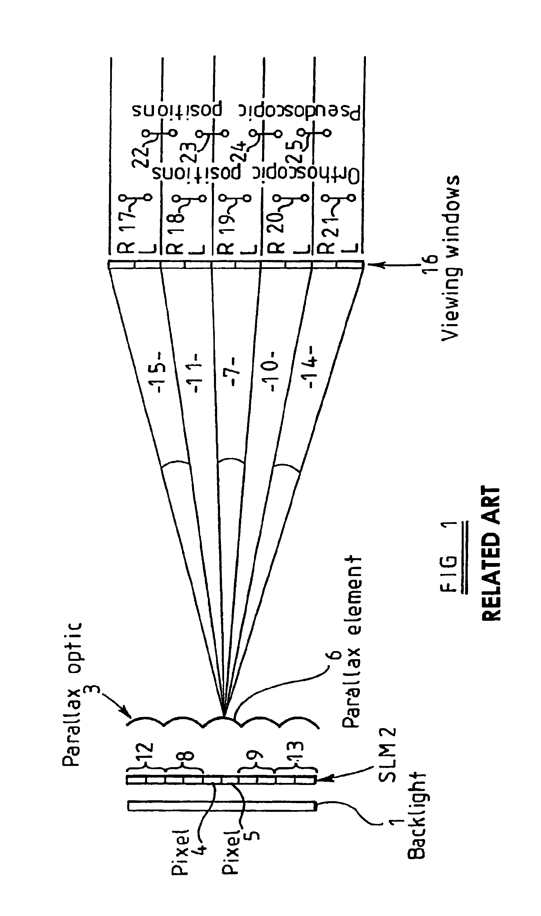
[0051]This is illustrated diagrammatically in FIG. 6 for a parallax optic in the form of a parallax barrier. The lateral positions of barrier slits 32 and pixels of the SLM 2 are illustrated at (a) for the image displaying and generating portion of the display, at (b) for the VPI shown in FIG. 4, and at (c) for the VPI shown in FIG. 5. In (b) and (c), those red pixels which cooperate with the slits of the VPI portion of the barrier to provide the usual indication to the observer are shaded. Thus, in FIG. 6(c...


PUM


Abstract

An autostereoscopic display comprises an SLM which is controlled to provide an image display and a signal display. A parallax optic has a first portion which cooperates with the image display to form a plurality of viewing windows. A second portion of the parallax optic forms first and second images visible to an observer to allow the observer to distinguish between a desired orthoscopic viewing zone and undesirable viewing positions such as pseudoscopic positions. The pitch of parallax elements in the second portion is one and a half times the parallax element pitch in the first portion.

Description

BACKGROUND OF THE INVENTION[0001]1. Field of the Invention[0002]The present invention relates to an autostereoscopic display. Such a display may comprise an autostereoscopic three dimensional (3D) display and maybe used, for instance, in 3D television, medical imaging, computer games, telephony, scientific visualisation, virtual reality and office automation equipment.[0003]2. Description of the Related Art[0004]A known type of autostereoscopic 3D display is shown in FIG. 1 of the accompanying drawings. The display comprises a diffuse back light 1 disposed behind a spatial light modulator (SLM) 2, for instance in the form of a liquid crystal display (LCD). The SLM 2 comprises an array of picture elements (pixels), for instance as disclosed in European Patent No. 0 625 861 in which the pixels are arranged in columns such that adjacent columns are substantially contiguous with each other in the lateral or horizontal direction.[0005]A parallax optic 3, for instance in the form of a len...

Claims


Application Information

Patent Timeline
IPC IPC(8): H04N13/00G02B30/25H04N13/04G02B27/22
CPCH04N13/0404H04N13/0409H04N13/0422H04N13/0454H04N13/305H04N13/324H04N13/31H04N13/359
Inventor JONES, GRAHAM ROGER
Owner SHARP KK
Why Eureka
Try Eureka