Apparatus and method for feeding wire in treatment liquid

a technology of apparatus and wire, which is applied in the direction of liquid/fluent solid measurement, fluid pressure measurement, peptides, etc., can solve the disadvantage of wire w jamming between the upper roller a′ and the lower roller c′, and the tensile force of the wire is released to looseness, etc. problems, to achieve the effect of convenient maintenance, easy replacement of parts, and improved workability

Inactive Publication Date: 2005-08-16
GOTO DENISH CO LTD
View PDF2 Cites 0 Cited by
  • Summary
  • Abstract
  • Description
  • Claims
  • Application Information

AI Technical Summary

Benefits of technology

[0033]Now, operational effects of the present invention will be discussed. Since the invention enable a constant appropriate tensile force to the wire without looseness of the wire at a pause of the apparatus, the apparatus can correctly feed the wire without disengagement of the wire from a predetermined feeding path not to exert an excessive force on the wire to cause no damage of the wire. The apparatus also enables a continues feeding of the wire with no damage thereof, enabling an improved workability, an easy replacement of parts, an easy maintenance, a simple construction, and an easy manufacturing and assembling with a reduced cost. The lubricity of the electrodeposition liquid contained in the electrodeposition liquid bath serves to smoothly feed the wire through the guiding conduit. The plurality of wires are moved through the plurality of tubular conduits in the treatment liquid bath. This improves the workability of the apparatus, since each wire can be independently controlled in transfer speeds and times, pauses, and restart timings according to the size of the wire. Furthermore, the tubular conduit can be easily formed to have a smooth curvature and can simplify the fitting and replacement of parts with an easy maintenance thereof.
[0034]In addition, the electrodeposition liquid is quickly introduced into the tubular conduit by a siphon effect so that the lubricity of the electrodeposition liquid enables a less friction force exerted on the wire, achieving a smooth transfer of the wire.
[0035]Moreover, the wire, which is supplied from the top of the first treatment liquid bath, is downwardly received in the tubular conduit 4 and turns upward to be smoothly moved in the second treatment liquid bath without an excessive tensile force exerted on the wire. The wire suffers neither damage nor breaking, allowing a constant continues transfer thereof.

Problems solved by technology

However, in the conventional wire feeding method employing the rolling supports of FIGS. 3 to 5, the tensile force of the wire is released to have a looseness when the motor stops its rotation.
Thereby, the wire w may not be automatically set at a correct position relative to the rollers a and c when the motor restarts the operation, resulted in an disadvantage that the wire can not be moved forward immediately due to the disengagement of the wire w from the channel b of the roller a.
In the conventional wire feeding method employing the rolling supports of FIGS. 6 to 8, when the wire has a larger diameter, the wire may possibly disengage from the channel b′ so that the wire w is disadvantageously jammed between the upper roller a′ and the lower roller c′.
This causes damage or breaking of the wire.
Thus, when the wire w is disengaged from the channel b″, the wire is jammed between the teeth of the gears, disadvantageously causing damage or breaking of the wire.

Method used


Image

  • Apparatus and method for feeding wire in treatment liquid
  • Apparatus and method for feeding wire in treatment liquid
  • Apparatus and method for feeding wire in treatment liquid

Examples


Embodiment Construction

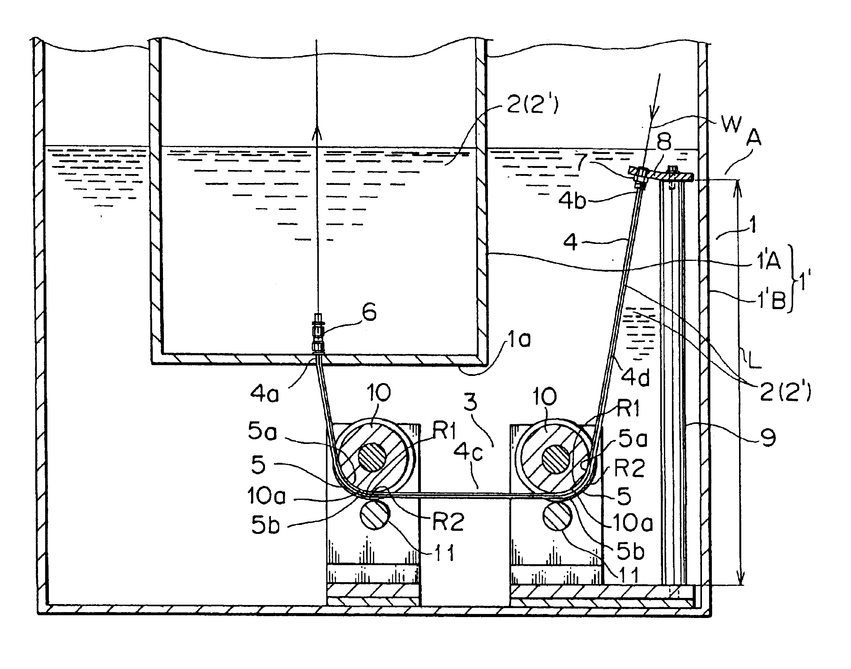
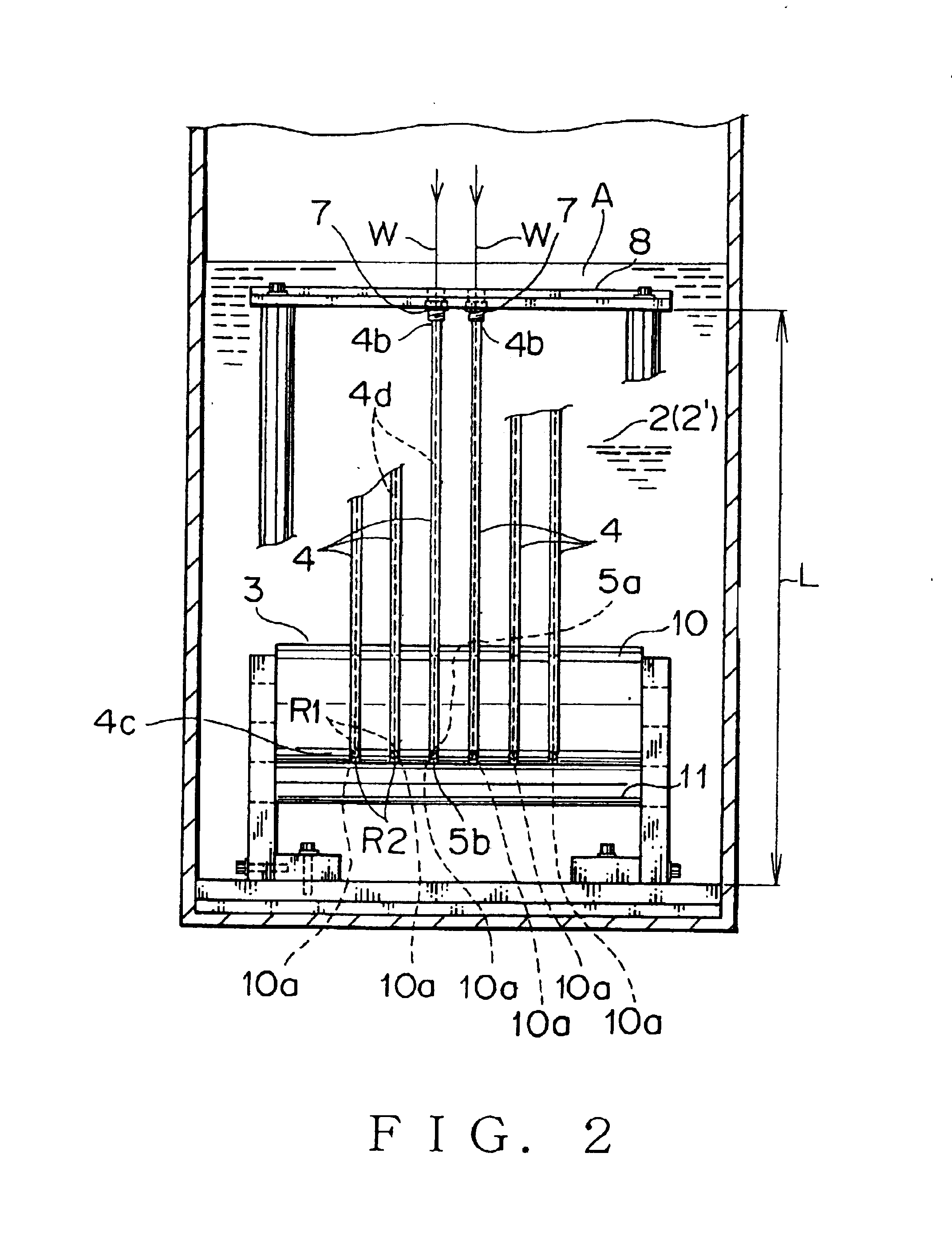
[0047]Referring to the accompanied drawings, an embodiment of the present invention will be discussed. FIGS. 1 and 2 show an embodiment of the present invention, which is adapted for providing an insulating film on an outer peripheral surface of an electrical conductor. In the embodiment, a liquid bath 1 contains a treatment liquid 2 and a wire guiding means 3 is disposed in the liquid bath 1. Through the wire guiding means 3, a wire is moved upward from a lower part 1a so that a desired treatment of the wire is provided like the conventional wire feeding methods shown in FIGS. 3 to 11.

[0048]In the embodiment, the treatment liquid 2 is an electrodeposition liquid 2′ and the liquid bath 1 is an electrodeposition liquid bath 1′ containing the electrodeposition liquid 2′. The liquid bath 1 filled with the electrodeposition liquid 2′ is appropriately used for providing an insulating film on an outer peripheral surface of the wire W. The electrodeposition liquid bath 1′ has an inner bath...


PUM

PropertyMeasurementUnit
electricalaaaaaaaaaa
tension forceaaaaaaaaaa
tensile forceaaaaaaaaaa

Abstract

The apparatus is provided with a wire guiding means disposed in a liquid bath for turning the direction of a wire to feed the wire into and out of the bath contained by the liquid. The wire guiding means includes a tubular conduit having a first open end disposed in the liquid, a second open end disposed above the liquid, and a middle curved portion for guiding the wire through the tubular conduit. The tubular conduit can be at least partially filled with the liquid. Preferably, the treatment liquid is an electrodeposition liquid. A plurality of the tubular conduits may be disposed in the bath substantially parallel with each other. Preferably the first open end is connected to a bottom portion of the bath through a coupling such that the treatment liquid in the bath can flows into the tubular conduit. The second open end is positioned higher than the first open end. Preferably, the apparatus further includes a main supporting shaft and a secondary supporting shaft positioned opposed to the main supporting shaft. The main supporting shaft has a channel defined on an outer peripheral surface thereof for receiving and contacting an inner curvature surface of the curved portion of the tubular conduit, while the secondary supporting shaft contacts an outer curvature surface of the curved portion to support the curbed portion of the tubular conduit therebetween.

Description

BACKGROUND OF THE INVENTION[0001]1. Field of the Invention[0002]The present invention relates to an apparatus and a method for feeding a wire in a treatment liquid contained in a liquid bath, particularly in an electrodeposition liquid bath for providing an insulating film on an outer peripheral surface of a wire like an electrical conductor. The apparatus can provide a constant appropriate tensile force to the wire without looseness so that the wire receives no excessive force to be reliably fed in the liquid with no damage of the wire.[0003]2. Related Art[0004]A known conventional method passes a wire like an electrical conductor in an electrodeposition liquid bath filled with an electrodeposition liquid for providing an insulating film on an outer peripheral surface of the conductor.[0005]In the method, the wire is supplied from a supply unit having a wire winding bobbin and is cleaned to eliminate dust and contaminants therefrom. Then, the wire passes through a direction changin...

Claims


Application Information

Patent Timeline
Patent Type & Authority Patents(United States)
IPC IPC(8): C25D7/06B65H57/12B21F23/00B21F99/00
CPCC25D7/0607
Inventor GOTO, YOSHIHIDE
Owner GOTO DENISH CO LTD
Why Eureka
Try Eureka