Solar cell module-mounting structure and solar cell module array

a solar cell and module technology, applied in the direction of heat collector mounting/support, lighting and heating apparatus, battery, etc., can solve the problems of limited cost reduction of conventional rack-mounted solar cell module structures using concrete members, so as to prevent the lateral movement of a plate-shaped member, suppress the cost increase of the rack, and prevent the effect of wire breakag

Inactive Publication Date: 2005-08-16
CANON KK
View PDF25 Cites 25 Cited by
  • Summary
  • Abstract
  • Description
  • Claims
  • Application Information

AI Technical Summary

Benefits of technology

[0018]The present invention provides a solar cell module-mounting structure capable of effectively preventing a solar cell module-mounting rack from being moved by a wind load; and a solar cell module array and a photovoltaic power generation system utilizing the structure.
[0031]The present invention can effectively prevent lateral movement of a plate-shaped member by a wind load to prevent the break of a wire and the like caused by such lateral movement.
[0032]Further, use of a concrete member for the plate-shaped member can suppress cost increase of the rack as much as possible, and in particular use of lightweight hollow concrete can improve installation workability and easiness of construction, resulting in cost reduction.
[0034]Furthermore, use of an adhesive for fixing the solar cell module on the surface of the plate-shaped member eliminates concern for stripping of the solar cell module by a wind load. In particular, use of an elastic adhesive or a double-sided tape with elasticity for fixing the solar cell module allows the adhesive layer to absorb difference in the coefficient of thermal expansion between the solar cell module and the plate-shaped member, resulting in the improvement of reliability. In addition, the solar cell module is fixed to the plate-shaped member at a surrounding part (circumferential edge) thereof, thereby allowing easy replacement of the solar cell module.
[0035]In addition, placement of an insulating member between one side of the plate-shaped member to be brought into contact with an installation surface and the installation surface can further reduce the leak current from a solar cell module having a partly exposed cable way or a wire having no insulation coating.

Problems solved by technology

However, not only the conventional rack-mounted solar cell module structure but also the conventional solar cell module-mounting structure using a concrete member as the rack has been limited in cost reduction, because the concrete body has to be prepared as a solar cell module rack having a desired size and an inclination angle.
However, in the case of forming the above-described solar cell module-mounting structure, the following problems have become clear.

Method used


Image

  • Solar cell module-mounting structure and solar cell module array
  • Solar cell module-mounting structure and solar cell module array
  • Solar cell module-mounting structure and solar cell module array

Examples


example 1

[0087]FIGS. 10 and 11 are schematic views for illustrating the solar cell module-mounting structure according to the present example. FIG. 10 is a view of the mounting structure when viewed from the side. FIG. 11 is a view of a part of the mounting structure when viewed from the light-receiving surface side of the solar cell module.

[0088]In FIGS. 10 and 11, numeral 1001 denotes a solar cell module; 1002 denotes a first row plate-shaped member; 1003 denotes a first row support member; 1008 denotes a second row plate-shaped member; 1009 denotes a second row support member; 1010 denotes a third row plate-shaped member; 1011 denotes a third row support member; 1012 denotes a fourth row plate-shaped member; 1013 denotes a fourth row support member; 1004 denotes a connection cable; 1005 denotes a ring sleeve; 1006 denotes the inclination angle of a plate-shaped member; 1007 denotes the distance between racks; 1016 denotes a parallel connection cable; 1017 denotes the direction of the seri...

example 2

[0110]In the present example, the inclination angle of a plate-shaped member, the distance between racks (direction of a support member) and the construction of a solar cell module were changed from the solar cell module-mounting structure of Example 1.

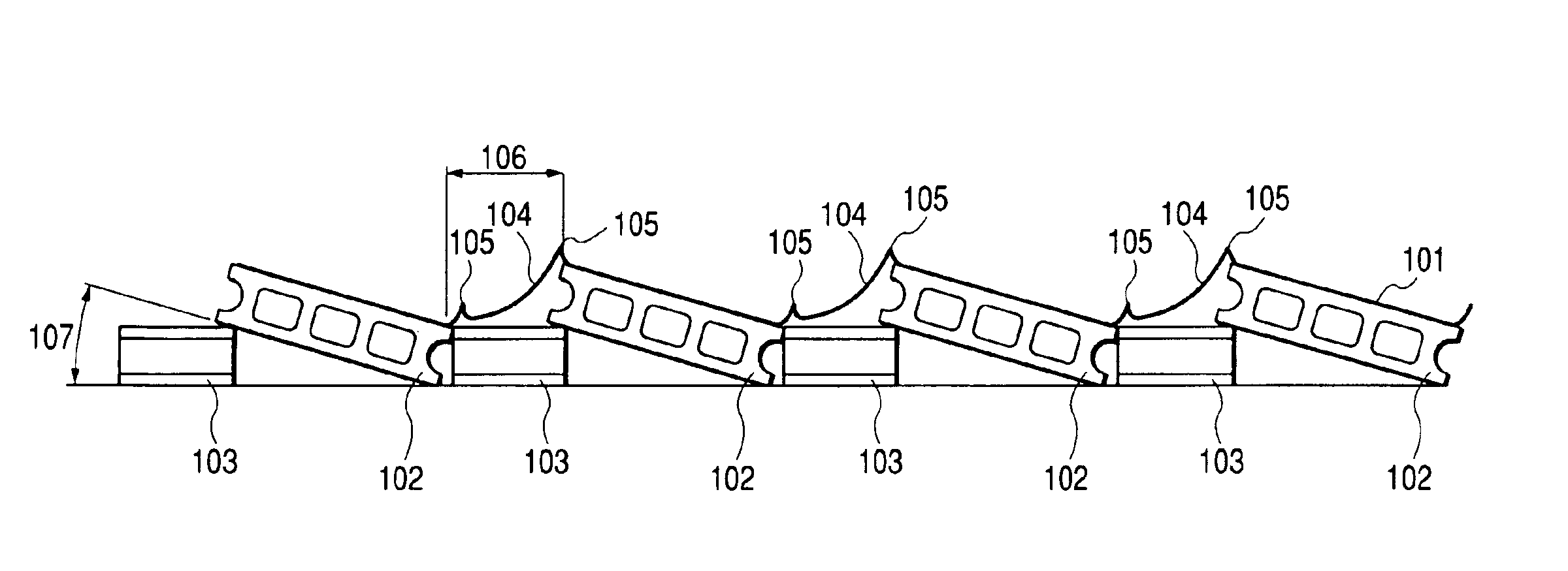
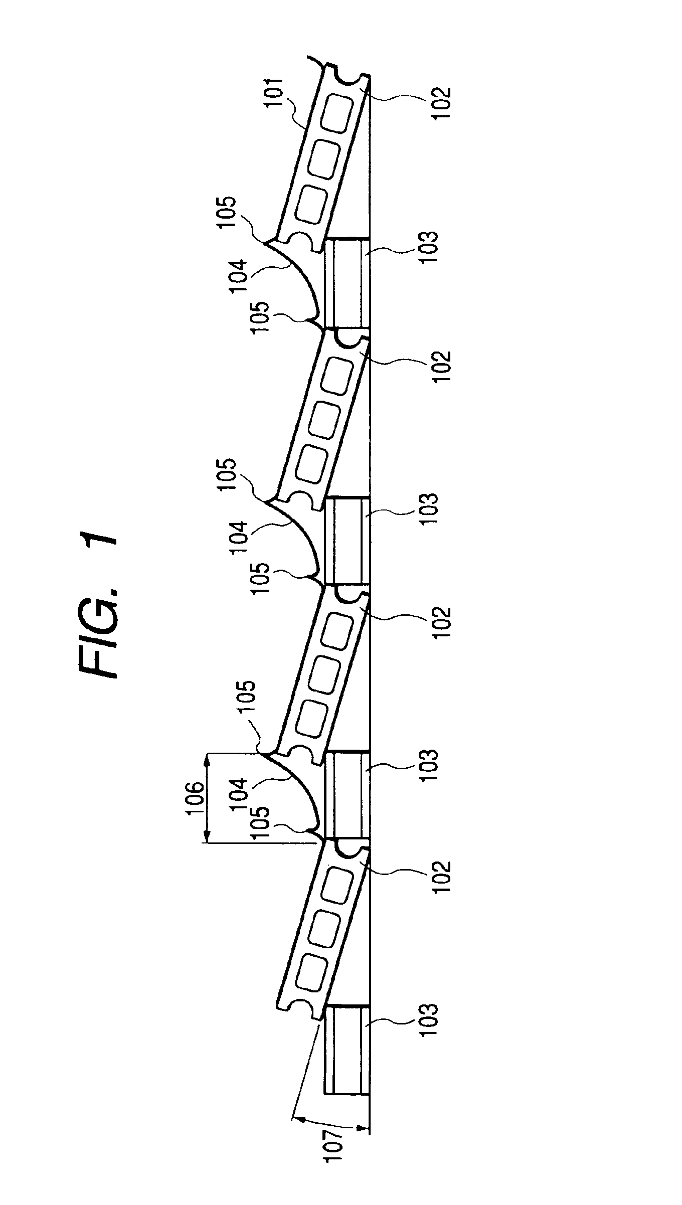
[0111]FIG. 13 is a side view of the solar cell module-mounting structure of the present example. In FIG. 13, numeral 1201 denotes a solar cell module; 1202 denotes a plate-shaped member; 1203 denotes a support member; 1204 denotes a connection cable; 1205 denotes a connection member (ring sleeve); 1206 denotes the distance between racks; and 1207 denotes the inclination angle of the plate-shaped member.

(Solar Cell Module)

[0112]FIGS. 14A and 14B are schematic views of the solar cell module for use in the present example. FIG. 14A is a plan view of the solar cell module, and FIG. 14B is a sectional view taken in the line 14B—14B of FIG. 14A.

[0113]A solar cell module 1301 has a semiconductor photoactive layer 1307 formed on a metal subst...

example 3

[0131]In the present example, the surface for installing a plate-shaped member was a concrete surface. FIG. 15 is a side view of the solar cell module-mounting structure of the present example. In FIG. 15, numeral 1401 denotes a solar cell module; 1402 denotes a plate-shaped member; 1403 denotes a support member; 1404 denotes a connection cable; 1405 denotes a connection member (ring sleeve); 1406 denotes the distance between racks; 1407 denotes the inclination angle of the plate-shaped member; 1408 denotes an insulating member; and 1409 denotes a concrete surface which is a plate-shaped member installing-surface.

[0132]In the present example, a rubber 1408, which is an insulating member having a thickness of 5 mm and a width of 50 mm, was placed between the side 1410 of the plate-shaped member 1402 to be brought into contact with the concrete surface 1409, and the concrete surface 1409 and between the support member 1403 and the concrete surface 1409, in order to further reduce the ...


PUM


Abstract

In a solar cell module-mounting structure, a solar cell module 101 is fixed on one surface of a plate-shaped member 102, the plate-shaped member 102 is placed on an installation surface so that one side of the plate-shaped member is in contact with the installation surface, a surface of the plate-shaped member 102 opposite to the solar cell module-fixing surface is in contact with a first support member 103, and out of surfaces including the one side of the plate-shaped member 102, at least a part of the surfaces in no contact with the first support member 103 is in contact with a second support member 103, thereby effectively preventing a solar cell module-mounting rack from being moved by a wind load.

Description

[0001]This application is a continuation of International Application No. PCT / JP03 / 03614, filed Mar. 25, 2003, which claims the benefit of Japanese Patent Applications No. 2002-090187, filed Mar. 28, 2002 and No. 2003-064313, filed Mar. 11, 2003.BACKGROUND OF THE INVENTION[0002]1. Field of the Invention[0003]The present invention relates to a solar cell module-mounting structure, a solar cell module array and a photovoltaic power generation system.[0004]2. Related Background Art[0005]The raised awareness of environmental issues has been spreading globally. Particularly, the concern about global warming phenomenon associated with CO2 emission is serious, and the desire for clean energy has been increasing. At present, a solar cell module can be expected as a clean energy source for safety and easy handling.[0006]Recently, various types of forms for mounting the solar cell module other than a roof-mounting type have been proposed as described below.[0007]FIGS. 2A and 2B are schematic ...

Claims


Application Information

Patent Timeline
Patent Type & Authority Patents(United States)
IPC IPC(8): H01L25/00H01L31/042H01L31/048F24J2/52
CPCF24J2/5237H02S20/00F24J2002/4687F24J2002/5292Y02E10/50Y10S136/291Y10S136/293Y02E10/47F24S25/11F24S2025/02F24S2080/012H02S20/24Y02B10/10
Inventor MAKITA, HIDEHISATAKABAYASHI, AKIHARUMATSUSHITA, MASAAKIMUKAI, TAKAAKIITOYAMA, SHIGENORI
Owner CANON KK
Why Eureka
Try Eureka