Hybrid synchronous/induction generator power plant

a hybrid generator and synchronous generator technology, applied in the direction of electric generator control, dynamo-electric converter control, magnetic circuit shape/form/construction, etc., can solve the problem that the synchronous generator cannot operate to supply the induction generator with sufficient reactive power

Inactive Publication Date: 2005-08-16
GENERAL ELECTRIC CO
View PDF15 Cites 5 Cited by
  • Summary
  • Abstract
  • Description
  • Claims
  • Application Information

AI Technical Summary

Benefits of technology

[0008]In addition to the above, a notable advantage of the present invention is that the efficiency advantages possible with a superconducting synchronous generator, and particularly an HTS generator, can compensate for the lower efficiency of an induction generator, resulting in a hybrid power plant with acceptable overall efficiency. The use of an HTS synchronous generator also avoids the shortcomings associated with the use of conventional synchronous generators if used to compensate for the reactive power demands of an induction generator intended for power generation, including high cost and large losses. More specifically, a synchronous generator cannot operate to supply an induction generator with sufficient reactive power to meet its VAR requirements and contribute to power generation. In addition, an HTS generator can be built with sufficient margin in the field ampere-turns to run in lower lagging power factors than conventional synchronous generators. Further advantages of the present invention associated with the use of an induction generator for power generation include a more robust generator construction at large frame sizes, the opportunity to operate at variable speeds to support grid stability during system transients, the opportunity to provide short-term overload by increasing the rotor (prime mover) speed, and cost reduction.
[0009]Other objects and advantages of this invention will be better appreciated from the following detailed description.

Problems solved by technology

More specifically, a synchronous generator cannot operate to supply an induction generator with sufficient reactive power to meet its VAR requirements and contribute to power generation.

Method used


Image

  • Hybrid synchronous/induction generator power plant
  • Hybrid synchronous/induction generator power plant

Examples


Embodiment Construction

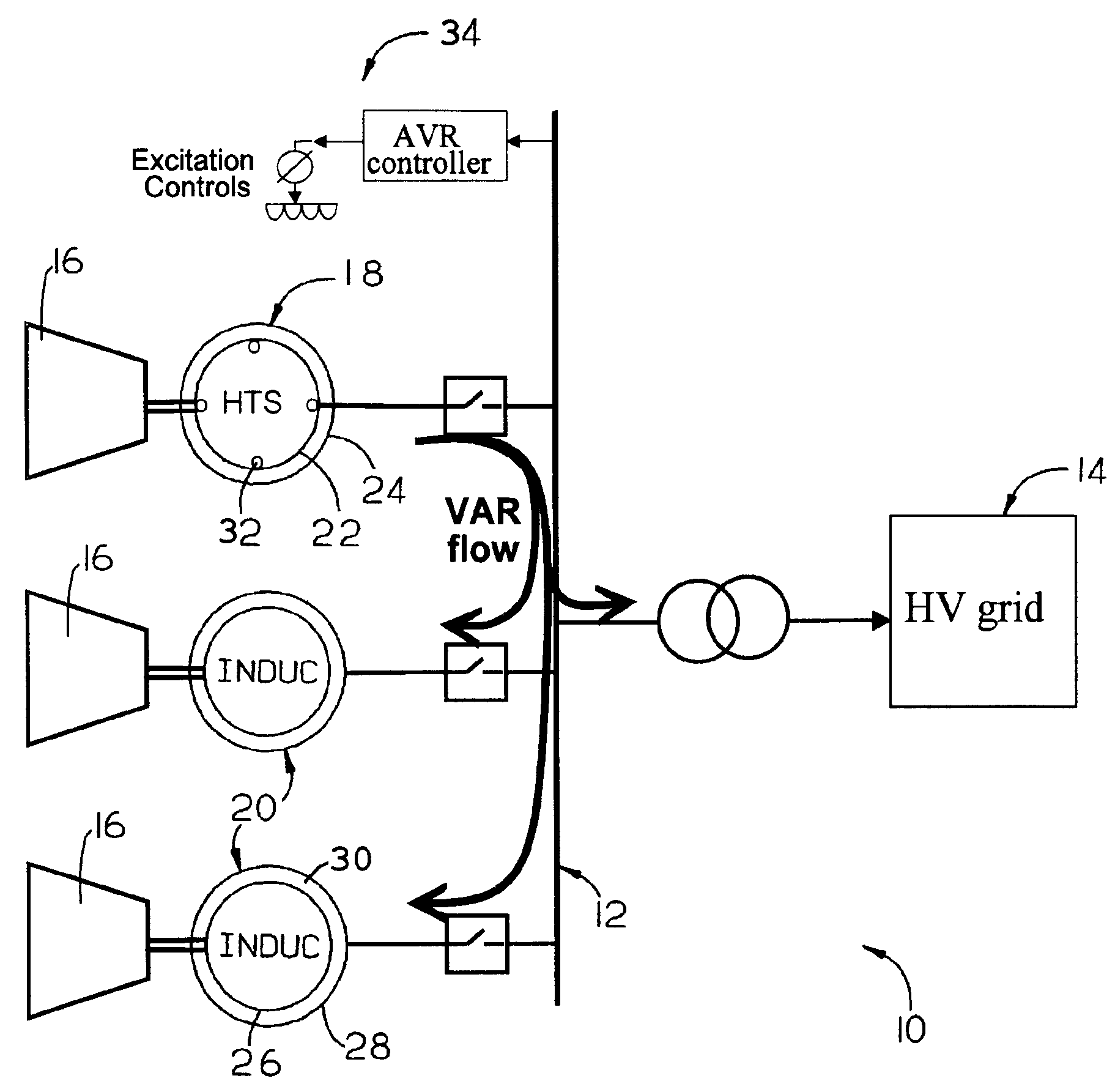
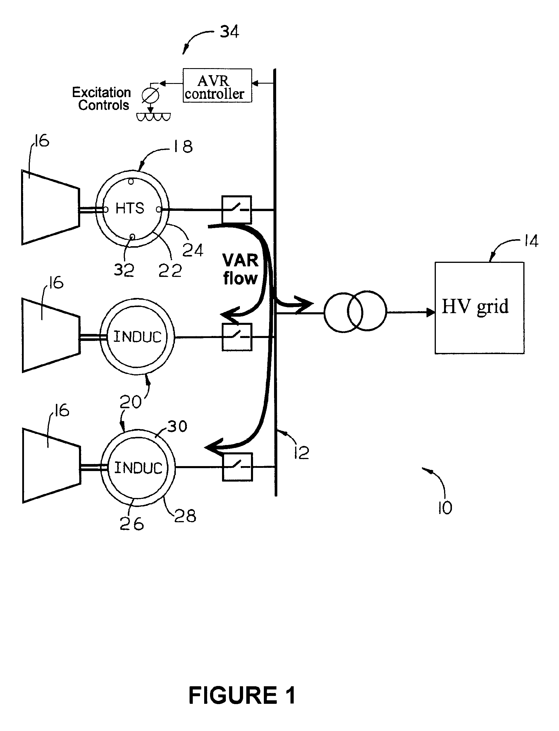
[0011]FIG. 1 schematically represents a portion of a power generation plant 10 connected to a high voltage (HV) power grid or distribution network 14. As the term is used herein, a power generation plant is a large-scale facility that serves as a primary supplier of high-voltage alternating current to a distribution or transmission network, typically a three-phase alternating current system as indicated. The plant 10 represented in FIG. 1 differs from approaches for power generation with induction generators that involve reactive power compensation with capacitor banks, or synchronous condensers. FIG. 1 represents the power generation plant 10 as comprising a power generating unit 12 that includes prime movers 16, such as turbines, that individually drive a synchronous generator 18 and two induction generators 20. While a single power generating unit 12 is shown, the plant 10 could comprise any number of such units 12.

[0012]The synchronous and induction generators 18 and 20 each com...


PUM


Abstract

A power generation plant comprising a power generating unit that includes at least one first generator, such as an induction generator, coupled to at least one synchronous generator having a rotor with a superconducting (SC) coil. The induction generator and the SC synchronous generator are coupled so that the SC synchronous generator supplies the induction generator with reactive power. Sufficient reactive power is preferably generated by the SC synchronous generator to meet the demand of the induction generator for VARs, as well as permit the induction generator to have a relatively large airgap.

Description

BACKGROUND OF INVENTION[0001]1. Field of the Invention[0002]The present invention generally relates to power generation equipment and systems. More particularly, this invention relates to a power generation plant that makes use of one or more induction generators in combination with one or more superconducting synchronous generators, the latter of which are operated to produce sufficient reactive power to meet the VAR requirements of the induction generators.[0003]2. Description of the Related Art[0004]Virtually all large turbine-driven generators used in the production of electrical power are synchronous generators. Synchronous generators generally comprise a rotor that serves as a source of magnetic lines of flux produced by a wound coil carried on the rotor, and a stator that comprises a number of conductors in which an alternating current is induced by the rotor as it rotates within the stator, generating a rotating magnetic field in the narrow airgap between the stator and roto...

Claims


Application Information

Patent Timeline
Patent Type & Authority Patents(United States)
IPC IPC(8): H02P9/10H02J3/24H02J3/18H02J3/38H02P9/00H02P9/14
CPCH02J3/1885H02J3/38H02P9/102Y02E40/32Y02E40/60Y02E40/30
Inventor SIVASUBRAMANIAM, KIRUBAWANG, YUWEEBER, KONRAD
Owner GENERAL ELECTRIC CO
Why Eureka
Try Eureka