
Partial discharge detection test link, partial discharge detection system and methods for detecting partial discharge on a power cable

a technology of partial discharge and detection system, which is applied in the direction of electrical testing, transmission, instruments, etc., can solve the problems of external damage to cables or contamination, one or more latent defects may occur within the dielectric, and defects can subsequently be introduced

Inactive Publication Date: 2005-08-16
PRYSMIAN CABLES & SYST
View PDF9 Cites 12 Cited by
  • Summary
  • Abstract
  • Description
  • Claims
  • Application Information

AI Technical Summary

Benefits of technology

[0010]Another object of the invention is to provide a partial discharge detection system and methods for minimizing risks of injury to living beings as well as risk of damage to the power cable circuit while being tested.
[0017]Yet another method of the invention detects partial discharge on a plurality of energized power cables positioned in an enclosure defined by an arrangement of walls. The method includes the steps of connecting respected ones of the first accessory components and the second accessory components to each other using a plurality of electrically insulative connectors; directly electrically connecting the respective ones of the first accessory components and the second accessory components to each other using respective ones of the plurality of test links; positioning electrically insulative barriers between juxtaposed ones of the plurality of energized cables to inhibit flashover; detecting partial discharge of the plurality of energized power cables at respective test links by generating partial discharge electrical signals; converting the partial discharge electrical signals adjacent the enclosure to alternative energy signals; transmitting the alternative energy signals to a location remote from the enclosure; and, interpreting the alternative energy signals at the remote location in a manner to measure the partial discharge of the respective energized power cables.

Problems solved by technology

If not, one or more latent defects may occur within the dielectric.
However, defects can subsequently be introduced.
Such defects include external damage to cables or contamination thereof as well as mishandling or misalignment of accessory components, particularly during installation.
It is impractical to conduct this test for long length of high voltage power cable using a portable test voltage source.
Many hazards are associated with energized power cable systems.
One hazard is standing power frequency voltages that exist between service links and from service links to earth which arises from normal operation of the power cable system.
Another hazard is transient voltages that exist between service links and from service links to earth which arises from switching operations, lightning strikes and the like.
Yet another hazard is severe electrical arcing as a result of flashover involving the service links.
Three, faults are likely to occur within the first few hours of the operation of the power cable system when PD testing is likely to be in progress.

Method used


Image

  • Partial discharge detection test link, partial discharge detection system and methods for detecting partial discharge on a power cable
  • Partial discharge detection test link, partial discharge detection system and methods for detecting partial discharge on a power cable
  • Partial discharge detection test link, partial discharge detection system and methods for detecting partial discharge on a power cable

Examples


Embodiment Construction

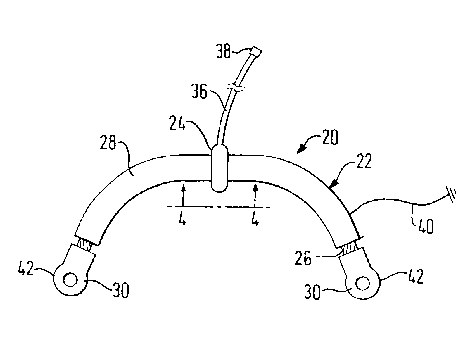
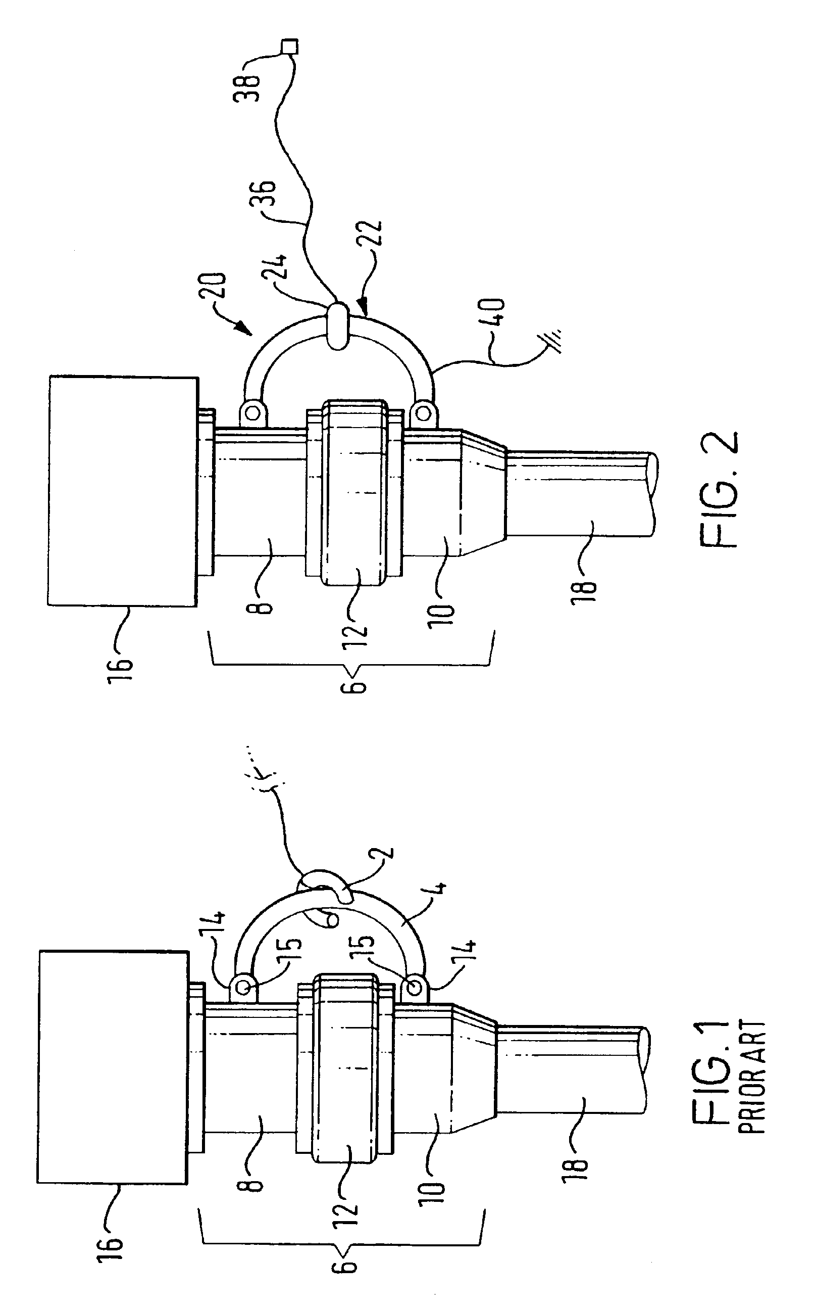
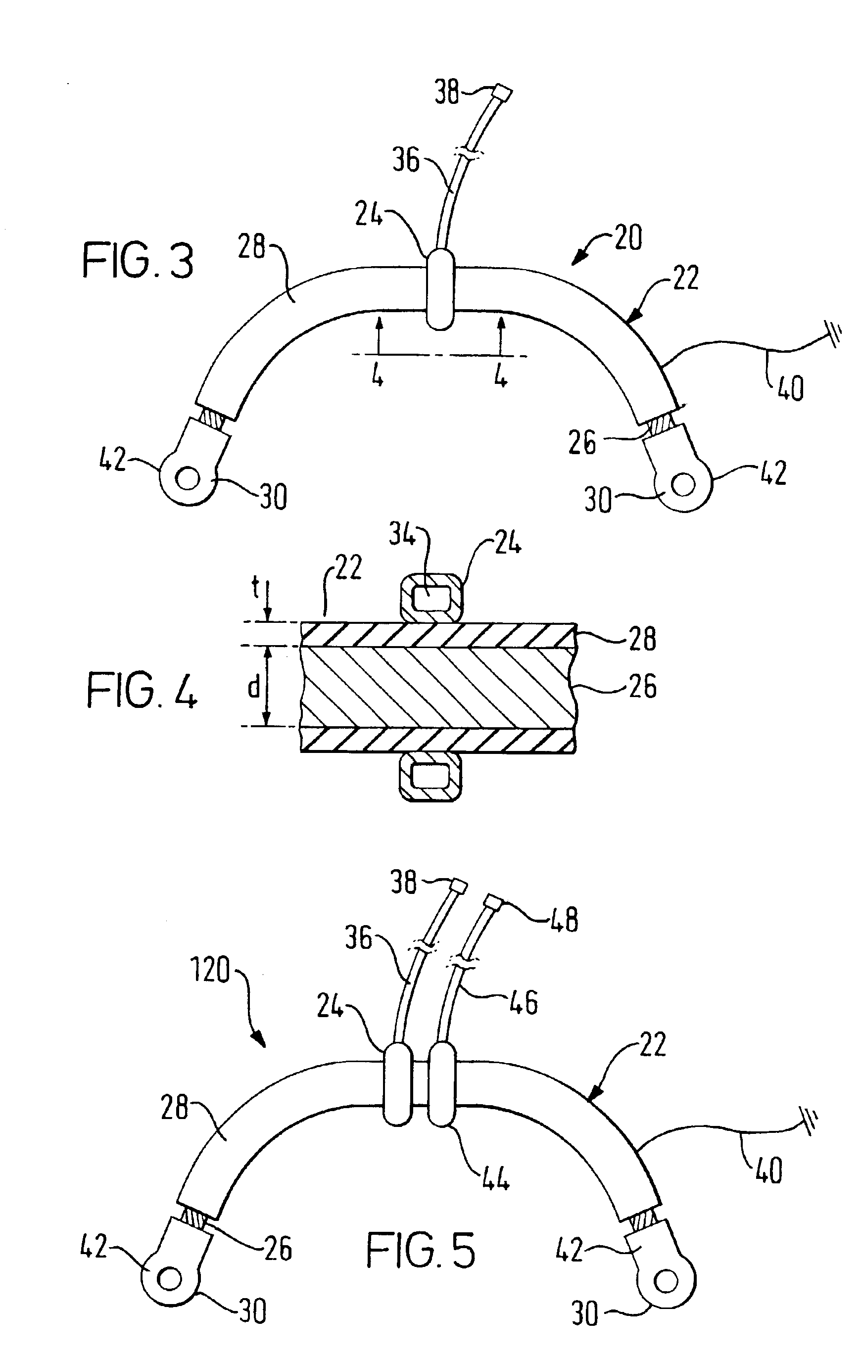
[0028]A partial discharge test link 20 of the invention is generally introduced in FIGS. 2-4. It is noted that identical elements designated FIG. 1 are identified with the same referenced numerals in FIG. 2. The partial discharge detection test link 20 of the invention detects partial discharge of the high voltage cable 18 at the power cable accessory 6. As shown in FIG. 3, the partial discharge detection test link 20 of the invention includes a conductor member 22 and a partial discharge sensor 24. The conductor member 22 includes an electrically conductive element 26 and an insulation 28 that surrounds and extends along the electrically conductive element 26. The electrically conductive element 26 has a pair of opposite ends 30. As shown in FIG. 2, a respective one of the ends 30 is adaptive for electrical connection to a respective one of the first and second accessory components 8 and 10 as is known in the art and illustrated in FIG. 1. As shown by way of example only, in FIG. 2...


PUM


Abstract

A partial discharge detection test link and system is disclosed to detect partial discharge of a power cable accessory. The power cable accessory includes a first accessory component and a second accessory component connected to each other. The partial discharge detection test link is a permanent or temporary substitute for a conventional service link, connects directly across the power cable accessory and includes a conductor member and a partial discharge sensor. The conductor member has an electrically conductive element and an insulation surrounding and extending along the electrically conductive element. The electrically conductive element is electrically connected directly between the first and second accessory components. The partial discharge sensor is disposed about the conductor member and has the electrically conductive element as a primary winding and a secondary winding with the insulation positioned between the primary and secondary windings.

Description

RELATED APPLICATIONS[0001]Priority is claimed to PCT International Application No. PCT / GB01 / 00321, filed Jan. 26, 2001.BACKGROUND[0002]The invention relates to apparatuses and methods for detecting partial discharge on a power cable. The apparatuses and the methods are particularly useful for detecting partial discharge on installed high-voltage power cables. More particularly, the apparatuses relate to a partial discharge detection test link and a partial discharge detection system.[0003]For satisfactory long-term performance extruded dielectric power cable systems at stress levels used in modern extra-high-voltage cross-linked polyethylene (XLPE) cable systems, it is necessary to maintain high purity levels of material and precision of manufacture. If not, one or more latent defects may occur within the dielectric. For quality assurance, the cables themselves as well as the accessory components are rigorously tested electrically prior to installation. However, defects can subseque...

Claims


Application Information

Patent Timeline
Patent Type & Authority Patents(United States)
IPC IPC(8): G01R15/14G01R15/18G01R31/12G01R31/02
CPCG01R15/181G01R31/1272G01R15/14G01R31/021G01R31/58
Inventor GREGORY, BRIANBARCLAY, ANDREW LESLIE
Owner PRYSMIAN CABLES & SYST
Learn More