
Dual frequency band inverted-F antenna

a technology of inverted antenna and frequency band, which is applied in the structure of radiating elements, elongated active element feed, and resonance antennas, etc., can solve the problems of unbreakable limitation of one-quarter signal, inability to effectively shrink, and limited antenna size of communication products, so as to achieve the effect of reducing the resonance frequency

Active Publication Date: 2005-08-16
GEMTEK TECH CO LTD
View PDF6 Cites 116 Cited by
  • Summary
  • Abstract
  • Description
  • Claims
  • Application Information

AI Technical Summary

Benefits of technology

[0012]In one embodiment of the present invention, the dual frequency band inverted-F antenna can include a substrate, a ground metal, a vortical metal structure, a short circuit leg, and a feeding leg. The ground metal is formed on a lower surface of the substrate. The vortical metal structure, formed on an upper surface of the substrate, further has a short circuit end and an open circuit end, in which the open circuit end is located within the center of the vortical metal structure. The short circuit leg connects electrically the short circuit end of the vortical metal structure with the ground metal. The feeding leg extends along a predetermined direction of the vortical metal structure to couple with a feeding circuit on the substrate. By increasing the encircling number of the vortical metal structure, the induced coupling effect is then generated so that the equivalent wavelength of the high frequency signal becomes longer and thereby the resonance frequency thereof can be reduced, and hence a first frequency for the antenna to transmit / receive signals can be kept communicating at a lower frequency band while a second frequency can be still added for communicating at a higher frequency band.
[0013]In one embodiment of the present invention, the dual frequency band inverted-F antenna can include a substrate, a ground metal, a vortical metal structure, a short circuit leg, a feeding leg, and a terminal micro strip. The ground metal and the terminal micro strip are both formed but separated on a lower surface of the substrate. The vortical metal structure formed on an upper surface of the substrate further has a short circuit end and an open circuit end. The short circuit leg connects electrically the short circuit end of the vortical metal structure with the ground metal. The feeding leg extends along a predetermined direction of the vortical metal structure to couple with a feeding circuit on the substrate. The terminal micro strip connects electrically to the open circuit end through a first conductive aperture and has the function of adjusting the coupled impedance with the feeding circuit. By increasing the encircling number of the vortical metal structure, the induced coupling effect is then generated so that the equivalent wavelength of the high frequency signal becomes longer and thereby the resonance frequency thereof can be reduced. Hence, a first frequency can be introduced to communicate at a lower frequency band, and a second frequency can be also added to communicate at a higher frequency band.

Problems solved by technology

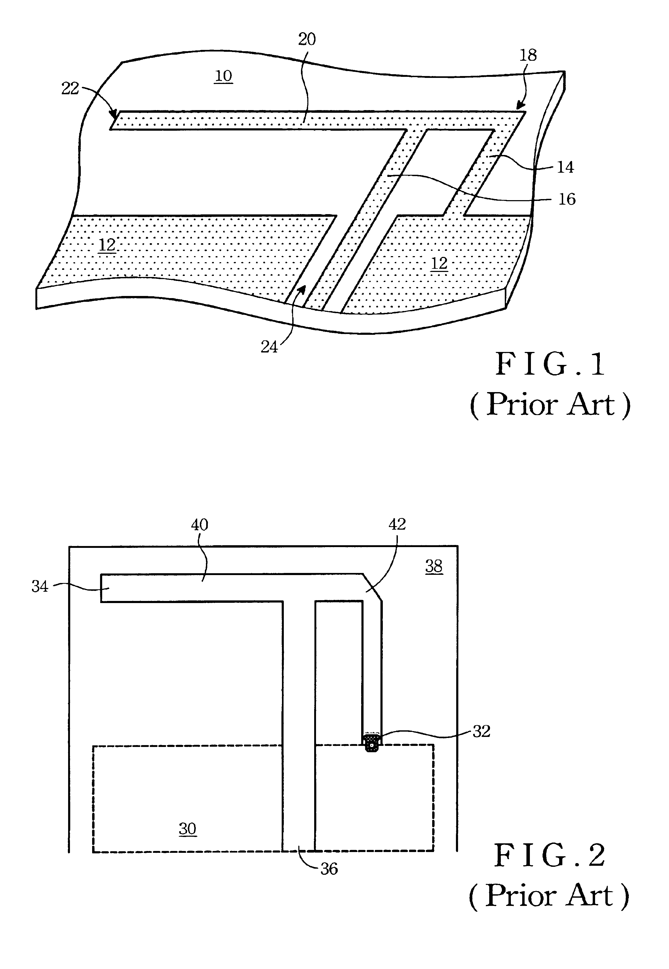
As the surface size of the compact printed antenna has a restriction that limits the length of the strip metal 20 to one quarter of the wavelength, the size of the antenna is thereby limited to a constant range of one quarter of the wavelength and thus cannot be shrunk effectively.
Through the development of passive elements in the contemporary integrated circuits has been targeting at the miniaturization of elements, yet the antenna size of the communication products is still restricted by the unbreakable limitation of one-quarter signal wavelength
Besides, the operating frequency of the aforementioned compact printed antenna is limited to a single frequency band.
Hence, the interference problems such as co-channel interference and next-channel interference become much more serious.

Method used


Image

  • Dual frequency band inverted-F antenna
  • Dual frequency band inverted-F antenna
  • Dual frequency band inverted-F antenna

Examples


first embodiment

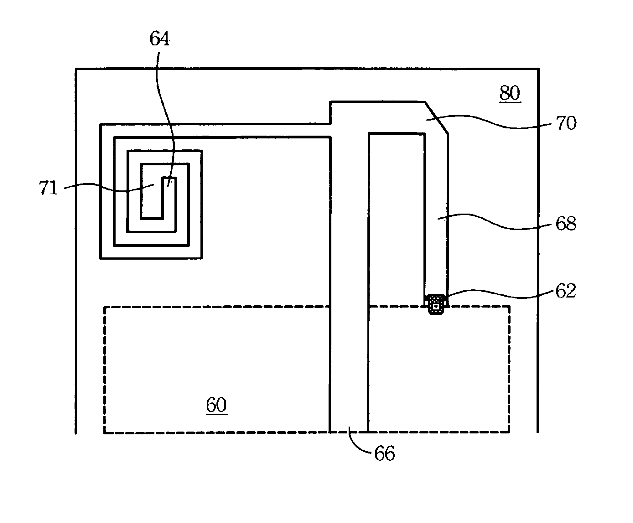
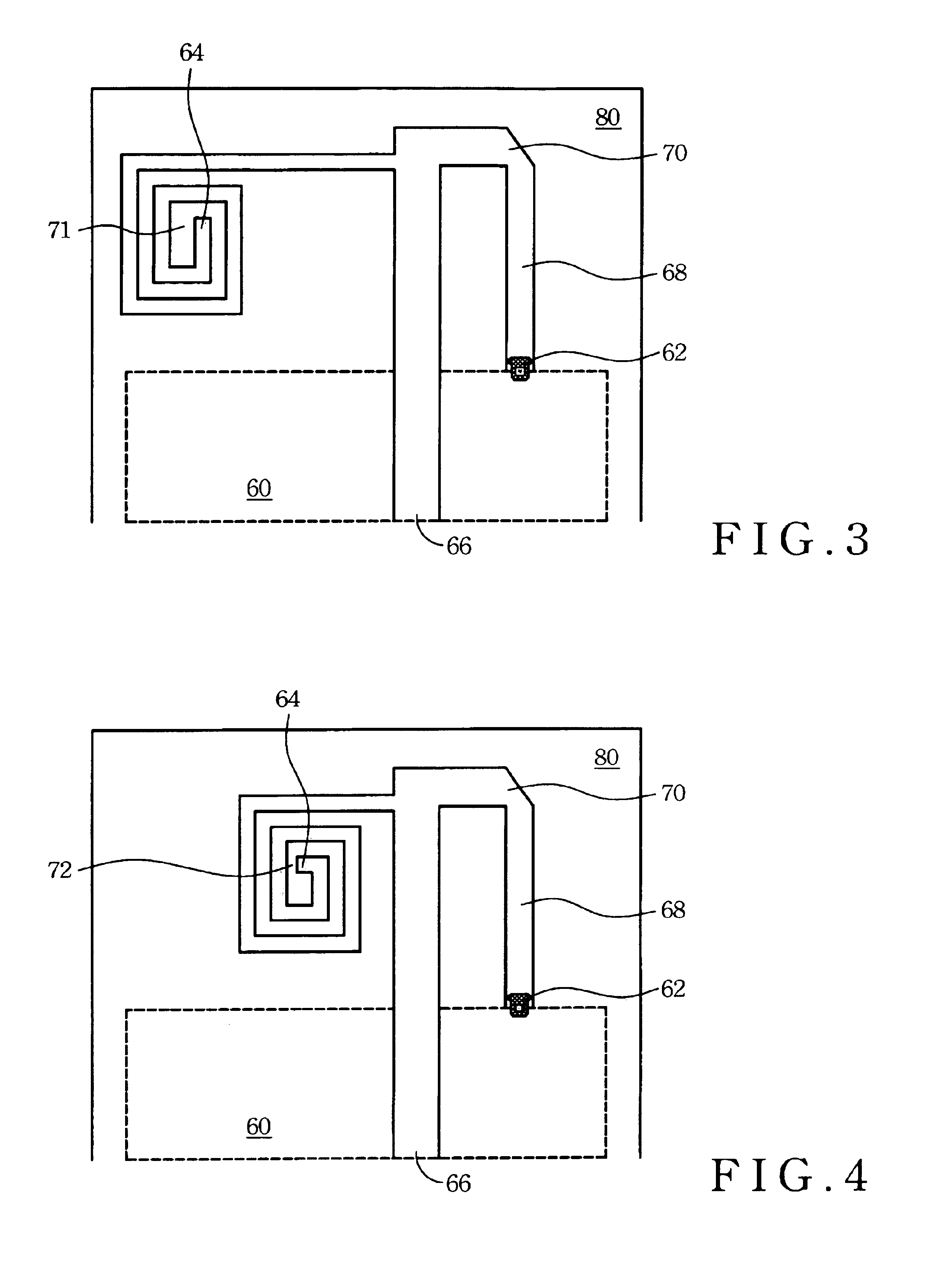
[0024]Referring to FIG. 3 for the present invention, the dual frequency band inverted-F antenna includes a substrate 80, a ground metal 60, a feeding leg 66, a short circuit leg 68 and a vortical metal structure 71. The substrate 80 is a dielectric material where the ground metal 60, the feeding leg 66, the short circuit leg 68 and the vortical metal structure 71 are formed thereon as printed circuits. Besides, the ground metal 60 shown in a dotted line in the drawing is formed on a lower surface of the substrate 80, and, on the other hand, the other parts of the antenna shown in dark color in the drawing are formed on an upper surface of the substrate 80. The vortical metal structure 71 is formed by an elongated metal strip bending into a vortical structure or made of a sheet of metal by punching into a vortical structure. The vortical metal structure 71 can further have an open circuit end 64 and a short circuit end 70 to form an open circuit-short circuit structure, in which the ...

third embodiment

[0030]Referring now to FIG. 7 for the present invention, the dual frequency band inverted-F antenna can include a substrate 90, a ground metal 84, a feeding leg 86, a short circuit leg 88, a vortical metal structure 94, and a terminal micro strip 76. The substrate 90 is a dielectric material, and the ground metal 84, the feeding leg 86, the short circuit leg 88, the vortical metal structure 94, and the terminal micro strip 76 are formed as printed circuits located on the substrate 90. Besides, the ground metal 84 and the terminal micro strip 76 shown in dotted lines are formed on the back side of the substrate 90, while the other parts of the antenna shown all in solid lines are formed on the front side of the substrate 90. The vortical metal structure 94 is formed by bending an elongated metal strip into a vortical structure or made of a sheet of metal by punching into a vortical structure. The vortical metal structure 94 further provides an open circuit end 78 and a short circuit ...


PUM


Abstract

A dual frequency band inverted-F antenna used for communicating a low frequency signal and a high frequency signal includes a substrate, a ground metal, a vortical metal structure, a short circuit leg, a feeding leg, and a terminal micro strip. The ground metal and the terminal micro strip are formed on the lower surface of the substrate. The vortical metal structure, formed on the upper surface of the substrate, further has a short circuit end and an open circuit end. The short circuit leg connects electrically the short circuit end of the vortical metal structure with the ground metal. The feeding leg extends along a predetermined direction of the vortical metal structure to couple with a feeding circuit on the substrate. The terminal micro strip connects electrically to the open circuit end through a first conductive aperture. By increasing the encircling number of the vortical metal structure, the coupling effect is generated so that the equivalent wavelength of the high frequency signal can be longer, thus the resonance frequency thereof can be reduced, and so a first frequency can be still kept communicating at a lower frequency band and a second frequency can also be added for communicating at a higher frequency band.

Description

BACKGROUND OF THE INVENTION[0001](1) Field of the Invention[0002]The invention relates to a design of printed inverted-F antenna, and more particularly to a printed inverted-F antenna for communicating in dual frequency band and having a function of adjusting coupled impedance.[0003](2) Description of the Prior Art[0004]Rapid innovation and development upon wireless communication technology have made mobile communication products as one of mainstream products nowadays. These mobile communication products include mobile phones, PDAs, notebooks, etc. They can couple with proper communication modules to link a Wireless Local Area Network (WLAN) for transmitting or / and receiving e-mail and instant information such as news, stocks quotations, and so on. In the art, the WLAN is an on-site wireless communication means that utilizes a WLAN card to transmit wirelessly vast data between computer systems. Apparently, in the WLAN, conventional complicated wiring webs have been replaced by wirel...

Claims


Application Information

Patent Timeline
Patent Type & Authority Patents(United States)
IPC IPC(8): H01Q5/00H01Q9/42H01Q1/38H01Q9/04H01Q5/357
CPCH01Q1/38H01Q5/357H01Q9/42
Inventor CHUNG, SHYH-JONGLEE, MING-CHOUHSIAO, JASON
Owner GEMTEK TECH CO LTD
Learn More