Optical information recording medium, and substrate and manufacturing method for the optical information recording medium

Inactive Publication Date: 2005-08-16
JVC KENWOOD CORP A CORP OF JAPAN
View PDF1 Cites 82 Cited by
  • Summary
  • Abstract
  • Description
  • Claims
  • Application Information

AI Technical Summary

Benefits of technology

[0012]Furthermore, another object of the present invention is to provide an optical information recording disk of a high density phase change type or a recording disk comprising both a recording/reproducing area and another area having a pit array for preventing the disk from illegal duplication and an address signal mentioned above so as to be able to

Problems solved by technology

However, a system having a same capacity as that of a DVD-ROM disk has not been developed yet.
In other words, a limited area of a disk can not be effectively utilized because of the area 24.
However, this method is defective in reflectivity, which is much inferior to a read only type disk or a write once type disk of utilizing dye.
Accordingly, the low reflectivity results in that a recording capa

Method used


Image

  • Optical information recording medium, and substrate and manufacturing method for the optical information recording medium
  • Optical information recording medium, and substrate and manufacturing method for the optical information recording medium
  • Optical information recording medium, and substrate and manufacturing method for the optical information recording medium

Examples


first embodiment

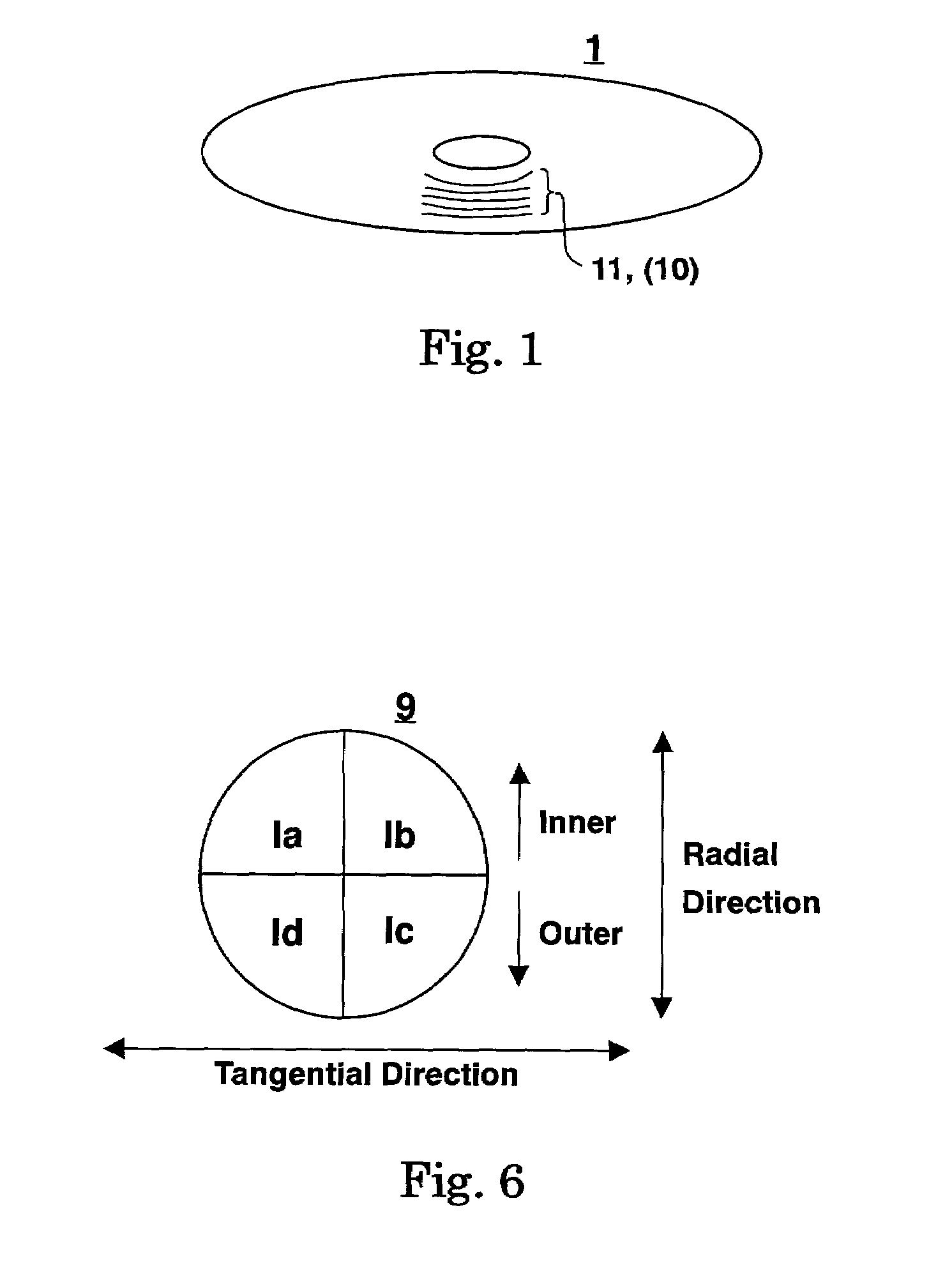
[0107]An application of the optical disk 1 of the present invention to a disk system utilizing a semiconductor laser irradiating a red laser beam is depicted. A wavelength λ of the red laser beam is 650 nm and a numerical aperture NA of an objective lens is 0.6. Accordingly, a reproduction spot diameter λ / NA of the laser beam is 1083 nm or 1.083 μm.

[0108]FIG. 15 is a cross sectional view of an optical disk according to a first embodiment of the present invention.

[0109]In FIG. 15, an optical disk 100 comprises a substrate 102, a recording layer 103, a resin layer 104 and a dummy substrate 105 with being laminated in order. Embossing on a surface of the substrate 102 forms a microscopic construction 10. The substrate 102 is a light path of a laser beam as far as the recording layer 103 and its thickness is 0.6 mm. A material of both the substrate 102 and the dummy substrate 105 is polycarbonate resin and its refractive index “n” at 650 nm is 1.58. The recording layer 103 has a laminat...

second embodiment

[0116]An application of the optical disk 1 of the present invention to a disk system utilizing a semiconductor laser irradiating a green laser beam is depicted. A wavelength λ of the green laser beam is 532 nm and a numerical aperture NA of an objective lens is 0.75. Accordingly, a reproduction spot diameter λ / NA of the laser beam is 709 nm or 0.709 μm.

[0117]FIG. 16 is a cross sectional view of an optical disk according to a second embodiment of the present invention. In FIG. 16, an optical disk 200 comprises a substrate 202, a recording layer 203, a resin layer 204 and a transmission layer 207 with being laminated in order. Embossing on a surface of the substrate 2 forms a microscopic construction 10. The transmission layer 207 is a light path of a laser beam as far as the recording layer 203 and its thickness is 0.1 to 0.12 mm. The transmission layer 207 is made from acetate resin and its refraction index “n” is 1.6. The recording layer 203 is composed of a phase change material, ...

third embodiment

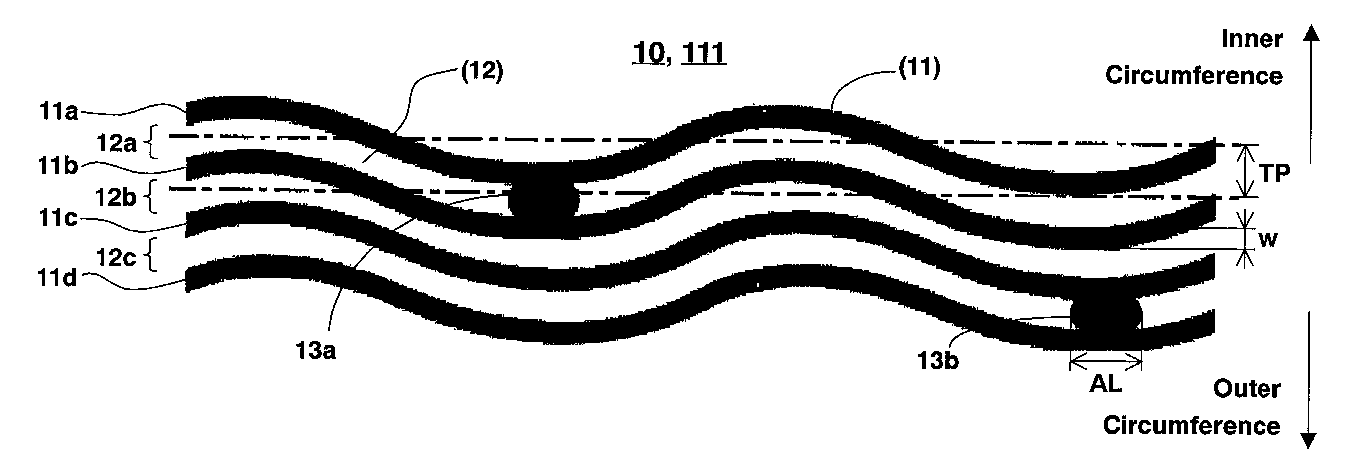
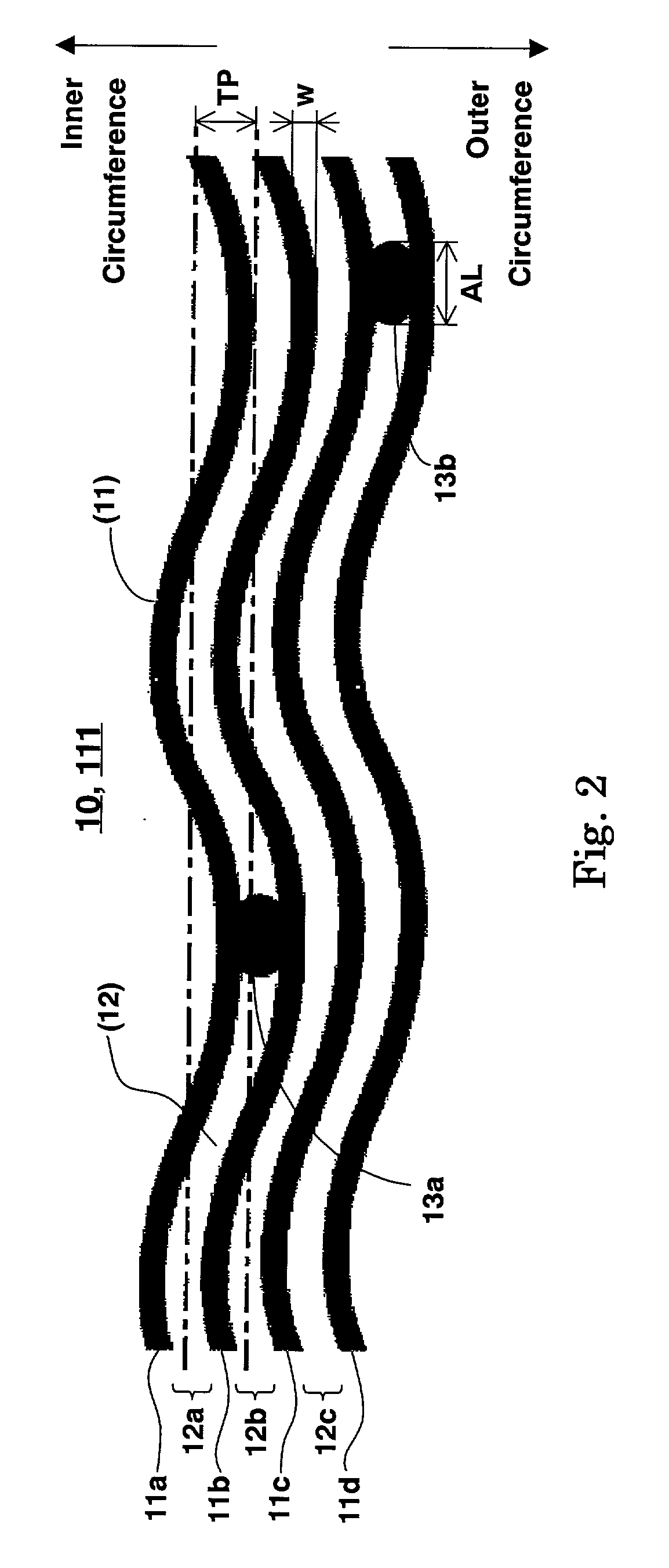
[0125]Two embodiments related to the optical disk 1, according to the present invention, comprising a substrate formed with address pits, which are allocated in sinusoidally deflected grooves and in between the grooves, a recording layer, which contains at least rewritable phase change material having a reflectivity of more than 15%, and a resin layer formed over the recording layer are explained and further a method extending the present invention over the embodiments is described above. An optical disk 300, which is provided with a particular pit array of preventing the optical disk from a dump copying, that is, duplicating whole software totally in an independent area and further an address pit is embedded in the pit array, is explained next as an application.

[0126]FIG. 20 is a plan view of an optical disk according to an embodiment of the present invention. In FIG. 20, an optical disk 300 comprises a first area 311 having a first microscopic construction 111 and a second area 31...


PUM


Abstract

In an optical disk including at least a rewritable phase change material and comprising a recording layer having a reflectivity of more than 15%, an address output value as an address pit signal component occupying in a reproduced signal in a non recording state is prescribed to be 0.18 though 0.27 or a numerical aperture of an address pit signal occupying in a reproduced signal in a non recording state is prescribed to be more than 0.3.

Description

BACKGROUND OF THE INVENTION[0001]1. Field of the Invention[0002]The present invention relates to an optical information recording medium being utilized for a recording and reproducing apparatus or a drive, which records an information in the optical information recording medium with moving the medium relatively and reads out the information from the medium, and a substrate and a manufacturing method for the optical information recording medium, particularly, relates to an optical information recording medium, which can be recorded and reproduced in a high density and a large capacity, and a substrate and a manufacturing method for the optical recording medium.[0003]2. Description of the Related Art[0004]Currently, there existed a system, which can optically record and reproduce information by using a disk shaped medium, as a system of an information recording medium for reading out information with moving the medium relatively. A disk system medium can be divided into several types ...

Claims


Application Information

Patent Timeline
IPC IPC(8): G11B7/013G11B7/26G11B7/007G11B7/24G11B7/24038G11B7/24079G11B7/24085
CPCG11B7/007G11B7/00736G11B7/00745G11B7/24G11B7/24079G11B7/24085G11B7/26G11B7/263G11B7/266G11B7/24035G11B7/00718G11B7/1374G11B7/24038
Inventor KONDO, TETSUYANAKAGAWA, EIJINAGANO, HIROFUMI
Owner JVC KENWOOD CORP A CORP OF JAPAN
Why Eureka
Try Eureka