Pump source for lasers

Inactive Publication Date: 2005-08-16
QINETIQ LTD
View PDF9 Cites 2 Cited by
  • Summary
  • Abstract
  • Description
  • Claims
  • Application Information

AI Technical Summary

Benefits of technology

[0038]Such a pump source arrangement is useful as it does not require a separate liquid dye gain medium to be located in close

Problems solved by technology

Firstly, there is the risk of a flashlamp explosion.
This creates a shockwave which can rupture the surrounding silica envelope and thereby causing a flashlamp explosion.
This risk of damage means that the level of electrical energy that can be used to drive the flashlamp must be limited.
Secondly, the optical spectrum from a flashlamp is thermal in nature and can be considered a quasi black body with a temperature of ˜20000 K. This means that a considerable fraction of the pump light resides in the hard ultra-violet region of the electromagnetic spectrum and this causes significant degradation and heating of the dye solution, as well as resulting in a poor absorption spectrum overlap (The dye solution that comprises the gain material consists of a dye and a solvent.
Hard ultra-violet radiation from the pump source wi

Method used


Image

  • Pump source for lasers
  • Pump source for lasers
  • Pump source for lasers

Examples


Embodiment Construction

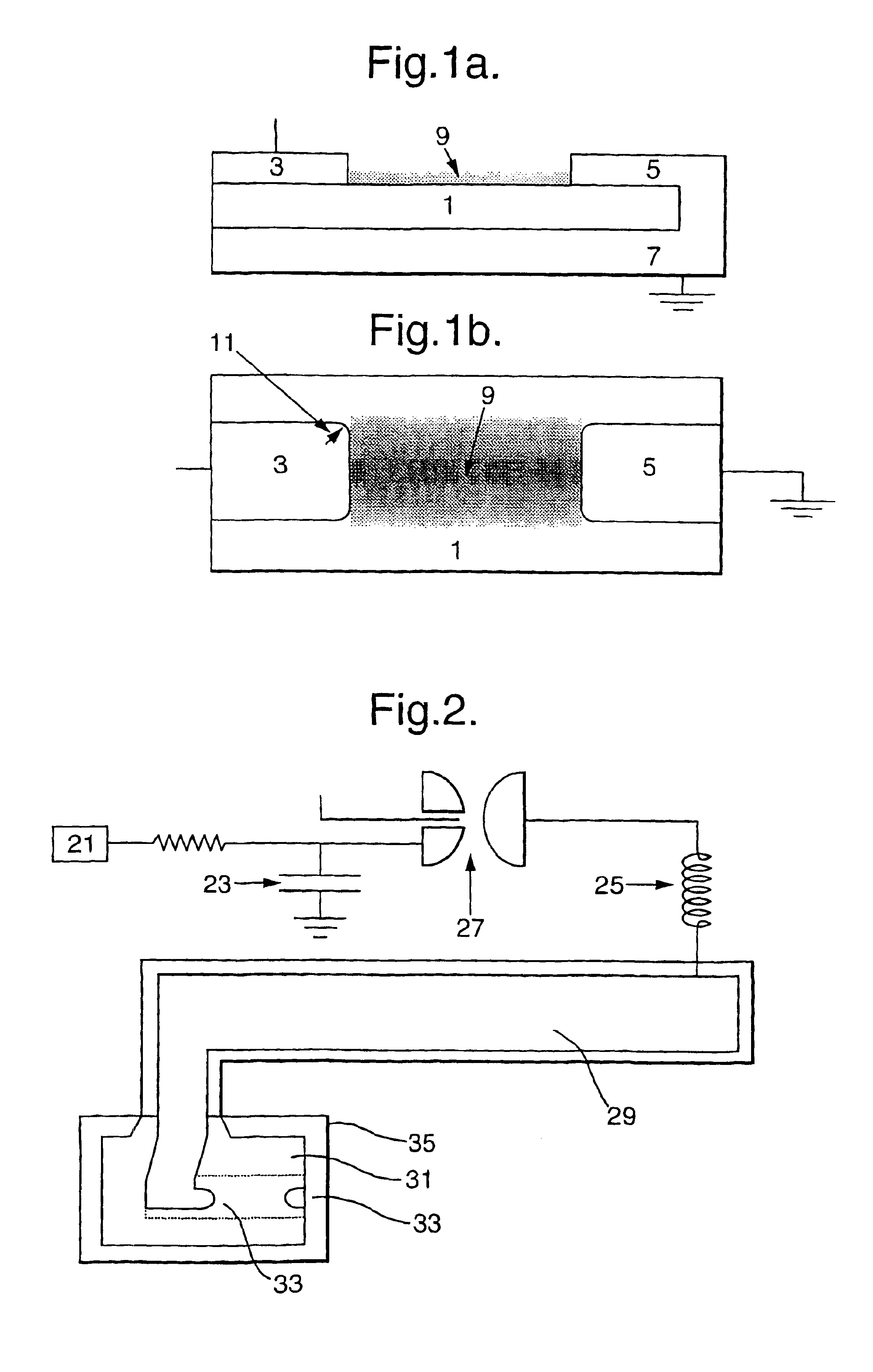
[0051]FIG. 1a shows a surface discharge assembly suitable for use as a pump source for lasers. A planar, dielectric substrate 1 is connected via electrodes 3,5 to an energy discharge source (not shown). Electrode 5 is connected to an earth plane 7. One surface of the substrate is in contact with a gas 9.

[0052]Upon initiation of a high voltage pulse from electrode 3 electrical breakdown of the gas 9 occurs in the region between the electrodes 3,5 as shown in FIG. 1b. A surface plasma is then formed.

[0053]FIG. 2 shows a pump source comprising a substrate / cover gas arrangement and a resonant circuit discharge. The figure shows an ALE 402L +50 kV power supply 21 connected to a 100 nF energy storage capacitor 23. The supply 21 and capacitor 23 are located in a high inductance (˜2.0 μH) section of the circuit. The inductance is generated by a loop of wire 25 and a switch 27. This switch 27 isolates the capacitor 23 from the rest of the circuit and comprises a gas filled, in line, trigatro...


PUM


Abstract

This invention relates to the field of lasers and in particular to the pump sources used in lasers. Many existing lasers use linear flashlamps in order to create population inversion in the gain medium of the laser. Such pump sources suffer from a number of drawbacks particularly when pumping dye lasers including explosive damage, long optical pulse length and inappropriate spectral emission. This invention provides a pump source for a laser which exploits the surface discharge phenomenon. A dielectric material (1) which is in contract with a gas (9) has electrical energy discharged across its surface in order to provide an electromagnetic emission which is then used to pump the gain medium. By varying the dielectric material or the cover gas used (amongst other variables) the surface emission can be used to pump the laser gain medium.

Description

BACKGROUND OF THE INENTION[0001]1. Field of the Invention[0002]This invention relates to the field of lasers and in particular to the pump sources used in lasers.[0003]2. Description of Related Art[0004]Lasers work by creating a so-called population inversion in a material (conventionally referred to as the “gain medium”) which is then stimulated to produce a coherent emission of photons. The pump source is the component of the laser which excites the gain material into a state of population inversion and different lasers utilise a variety of processes to create the population inversion. For example, the common He—Ne laser uses a high voltage electrical discharge to excite a He—Ne mixture in a discharge tube to population inversion.[0005]Typical flashlamp pumped dye lasers comprise several linear flashlamps which are symmetrically placed around a central cell containing dye (the gain medium). A reflector surrounds both the dye cell and flashlamps and directs light into the dye cell ...

Claims


Application Information

Patent Timeline
IPC IPC(8): H01S3/0915H01S3/16
CPCH01S3/09155H01S3/168
Inventor FULKER, DAVID JAMESVENNER, MARK RALPHFINLAYSON, ANDREW JAMESCASE, ANTHONY DAVID
Owner QINETIQ LTD
Why Eureka
Try Eureka