Method and apparatus for measuring motion of an object surface by multi-resolution analysis using a mesh model

a technology of object surface and mesh model, applied in image analysis, instruments, television systems, etc., can solve the problems of limiting the scope and utility of applications, frame-by-frame examination, and not providing sufficient accurate measures of face motion

Inactive Publication Date: 2005-08-16
ATR ADVANCED TELECOMM RES INST INT
View PDF5 Cites 15 Cited by
  • Summary
  • Abstract
  • Description
  • Claims
  • Application Information

AI Technical Summary

Benefits of technology

[0012]The present invention provides the means to measure the detailed motion of an object's surface, such as a human face, accurately and in real time from video image sequences using image processing and analysis software implemented on a computer. The measurement i...

Problems solved by technology

Though various attempts have been made to analyze face motions from sequences of video images, most attempts either have not been based on quantitative evaluation or they have been restricted to limited quantitative evaluation of facial features, pre-determined by some combination of statistical and artistic techniques.
Though such techniques can provide useful results, they often rely heavily on artistic rather than empirical techniques, they require tedious frame-by-frame examination, and they have not provided sufficiently accurate measures of face motion to be useful in coding dynamic attributes/properties of the face during, for example, spoken communication.
(1) The equipment necessary for measurement is not general purpose but is highly specialized, thus limiting the scope and utility of applicati...

Method used


Image

  • Method and apparatus for measuring motion of an object surface by multi-resolution analysis using a mesh model
  • Method and apparatus for measuring motion of an object surface by multi-resolution analysis using a mesh model
  • Method and apparatus for measuring motion of an object surface by multi-resolution analysis using a mesh model

Examples


Embodiment Construction

[0040]Hardware Configuration

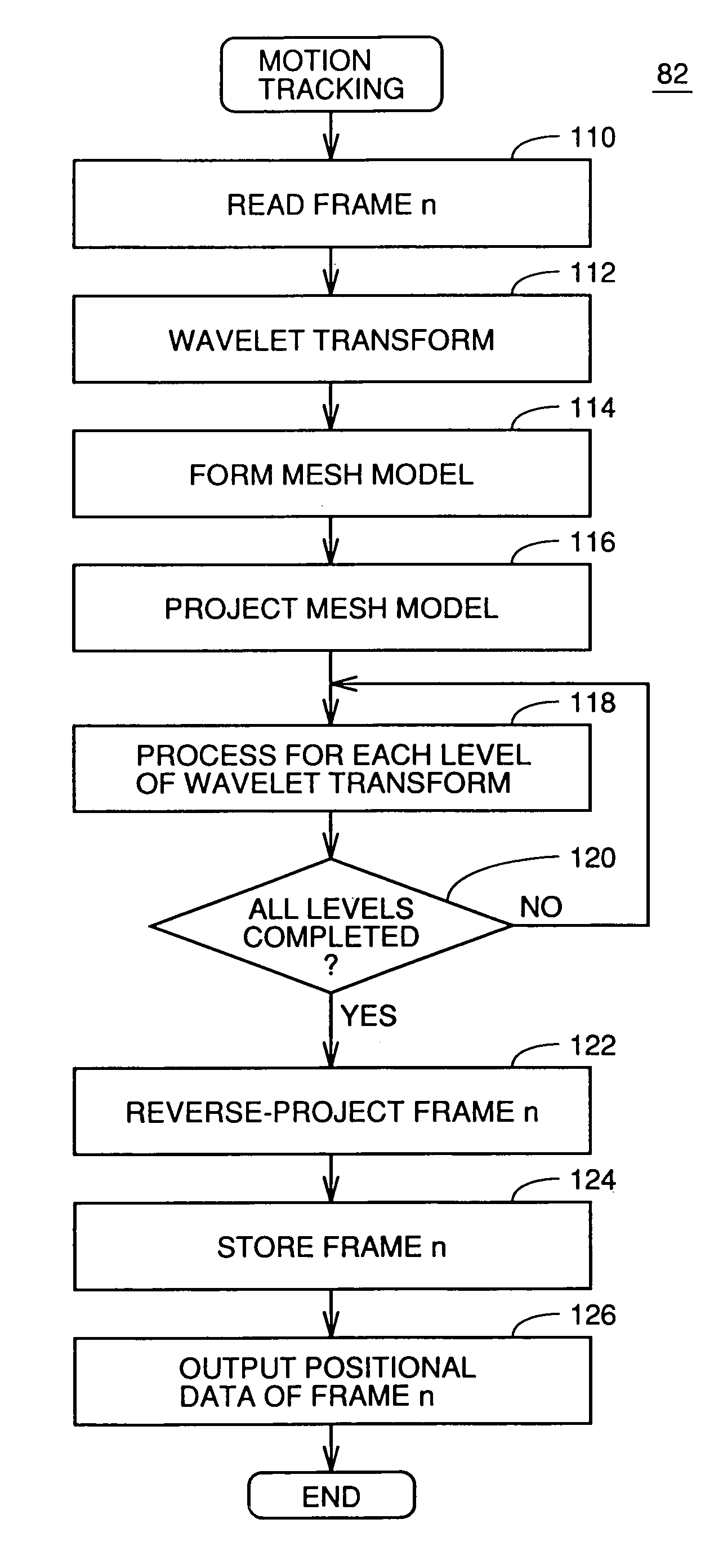
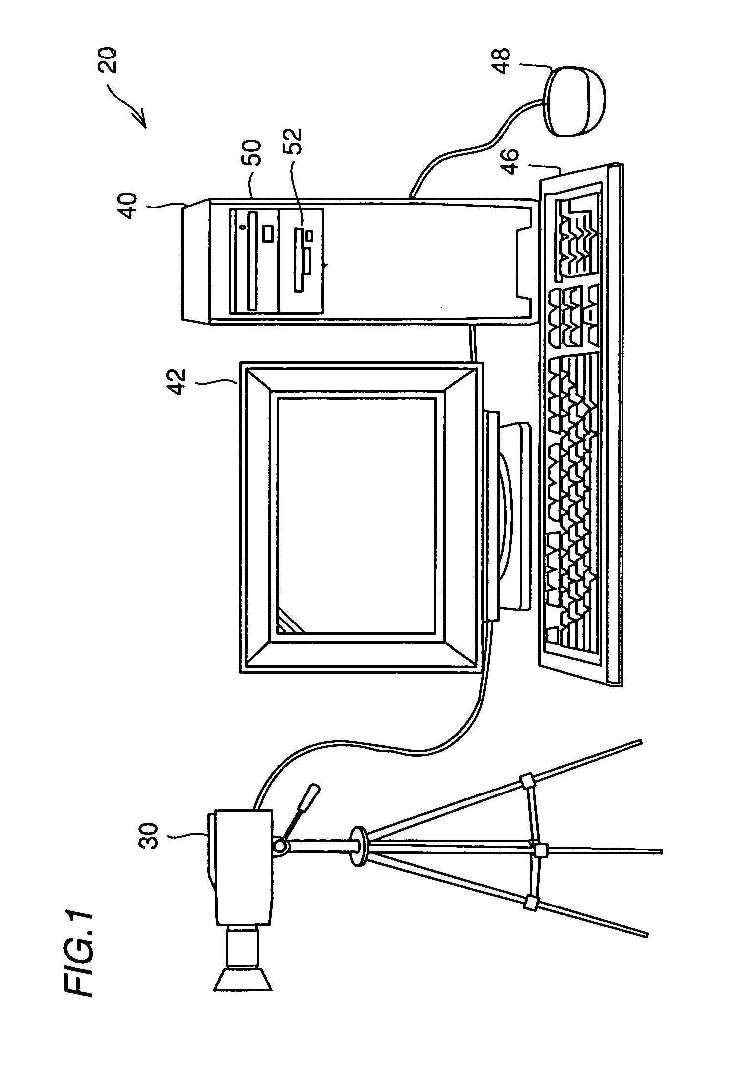
[0041]In the following, a facial expression measuring apparatus in accordance with the first embodiment of the present invention will be described. The facial expression measuring apparatus is implemented by software executed on a computer such as a personal computer or a work station, for measuring motion of each portion of a person's face (facial expression) from a video image sequence of that face. FIG. 1 shows the appearance of the facial expression measuring apparatus.

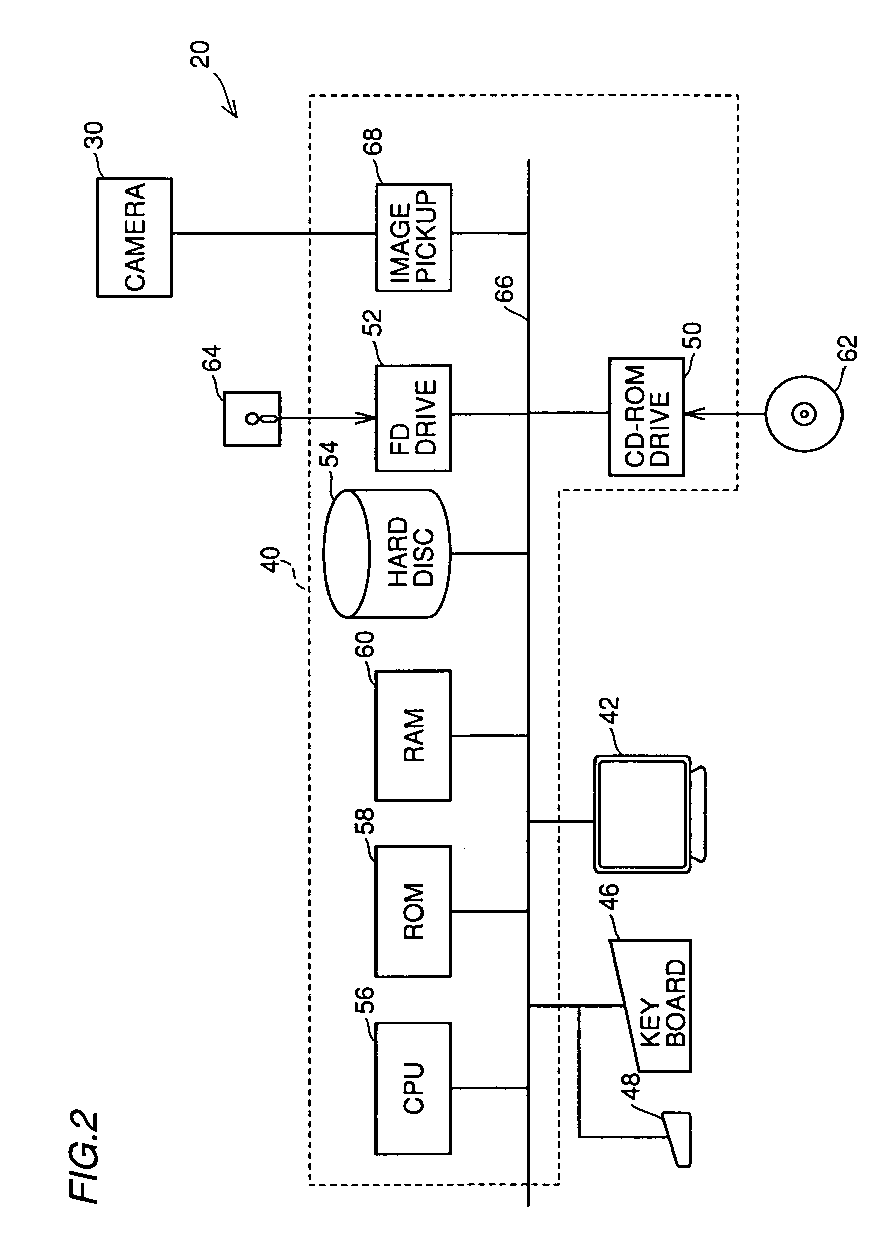
[0042]Referring to FIG. 1, the system 20 includes a computer body 40 including a CD-ROM (compact disc read-only memory) drive 50 and an FD (flexible disc) drive 52, a display 42 as a display apparatus connected to computer body 40, a keyboard 46 and a mouse 48 as input devices connected to computer body 40, and a video camera 30 for picking up an image connected to computer body 40. In the apparatus of the present embodiment, video camera 30 refers to a video camera including a CCD (cha...


PUM


Abstract

The method of measuring surface motion is for measuring motion of each portion of an object surface from a sequence of unit images of the object including first and second unit images, and includes the step of determining a plurality of measurement points in the image of the object of the first unit image. The plurality of measurement points have a hierarchical structure of a plurality of levels, with the upper level layer having larger number of measurement points than the lower level layer. The method further includes the step of determining points in the image of the object of the second unit image, corresponding to the measurement points of the first unit image of the lowest level among the plurality of levels of the hierarchical structure, and the step of repeating, starting from the level immediately above the lowest level up to the highest level, based on the points corresponding to the measurement points of the first unit image in the level immediately lower than the present level in the image of the object of the second unit image, points corresponding to the measurement points of the first unit image in the image of the object of the second unit image for each level.

Description

BACKGROUND OF THE INVENTION[0001]1. Field of the Invention[0002]The present invention relates to a process of measuring the motion of a deformable object's surface and, more particularly, the present invention relates to a field of image recognition for measuring, in real time, facial shape from images obtained by a video camera, for example.[0003]2. Description of the Background Art[0004]Human facial expression is extremely important in the communicative interactions of humans. Similarly, human facial expression is important in the so called man-machine interface.[0005]During face-to-face interaction, face motion conveys information at various levels. The transmitted information includes a person's emotional condition, position in a discourse, and while speaking, phonetic details about the speech sounds being produced.[0006]Though various attempts have been made to analyze face motions from sequences of video images, most attempts either have not been based on quantitative evaluati...

Claims


Application Information

Patent Timeline
IPC IPC(8): G06K9/00G06K9/46G06T7/20H04N7/30H04N19/60H04N19/51H04N19/533H04N19/54H04N19/635H04N19/85
CPCG06T7/2073G06T7/207
Inventor KROOS, CHRISTIANVATIKIOTIS-BATESON, ERICKURATATE, TAKAAKI
Owner ATR ADVANCED TELECOMM RES INST INT
Why Eureka
Try Eureka