Distributor purge valve

a technology of distributors and valves, applied in the field of valves, can solve the problems of affecting the operation of turbines, and affecting the reliability of spring-loaded checks,

Active Publication Date: 2005-08-23
JANSENS AIRCRAFT SYST CONTROLS
View PDF34 Cites 36 Cited by
  • Summary
  • Abstract
  • Description
  • Claims
  • Application Information

AI Technical Summary

Benefits of technology

[0016]The actuator piston moves within a piston chamber in the pilot air section. To prevent fuel from leaking through the interface between the fuel and pilot air sections into the piston chamber (and potential out of an ambient vent therein), an interstitial vent is disposed between the spool chamber and the piston chamber and two annular seals are disposed about the stem of the actuator piston on each side of the interstitial vent.
[0018]The valve operates by the spool moving from its initial position in which the distributor outlets are in communication with the inlet to the purge air section and closed off from the inlet to the fuel section so that high temperature purge air can be forced passed the downstream side of the spool and to the burners in the combustion can of the turbine engine to eliminate coking in these areas that may otherwise occur when the turbine engine is operated for prolonged periods in gaseous fuel mode controlled by a separate valve. The spool moves against the biasing spring under the force of the pilot air driven actuator piston and the force of the pressurized fuel so that fuel can flow, initially through the fill nozzles and then the outlet orifices, directly to the combustion can. The fuel section further includes a recirculation port in communication with the fuel inlet so that when the spool closes the outlet orifices and fill nozzles, fuel circulates through the fuel section past an upstream side of a valve section of the spool to prevent coking in this area as well. Proper and low maintenance operation of the valve (and the gas turbine) are further provided for by collecting and removing particles from the fuel stream.

Problems solved by technology

However, common spring-loaded checks may be unreliable, sticking in the open position or allowing some backwash into either of the fuel or purge lines.
Alternatively, the fuel cut-off valve may be operated by a pneumatic actuator in line with the check valve of the fuel line, however, this is also subject to coking and may introduce substantial pressure drops in the fuel flow.
The fuel cut-off valve also introduces a potential failure point to the turbine where, if pressure is lost to the pneumatic actuator, the turbine will cease operating.
This additional component and additional lines add significant cost, assembly and size to the system.

Method used


Image

  • Distributor purge valve
  • Distributor purge valve
  • Distributor purge valve

Examples


Embodiment Construction

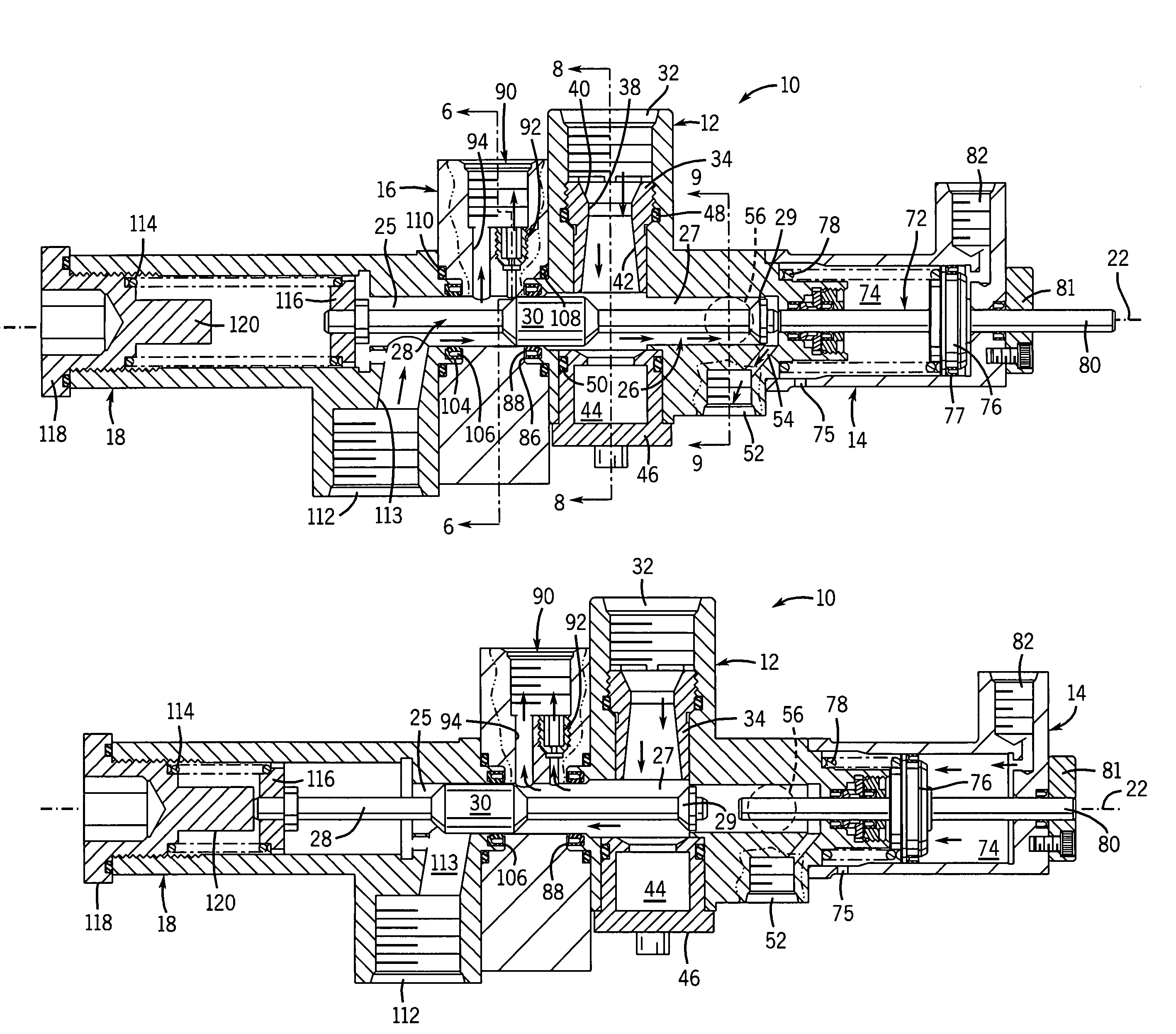
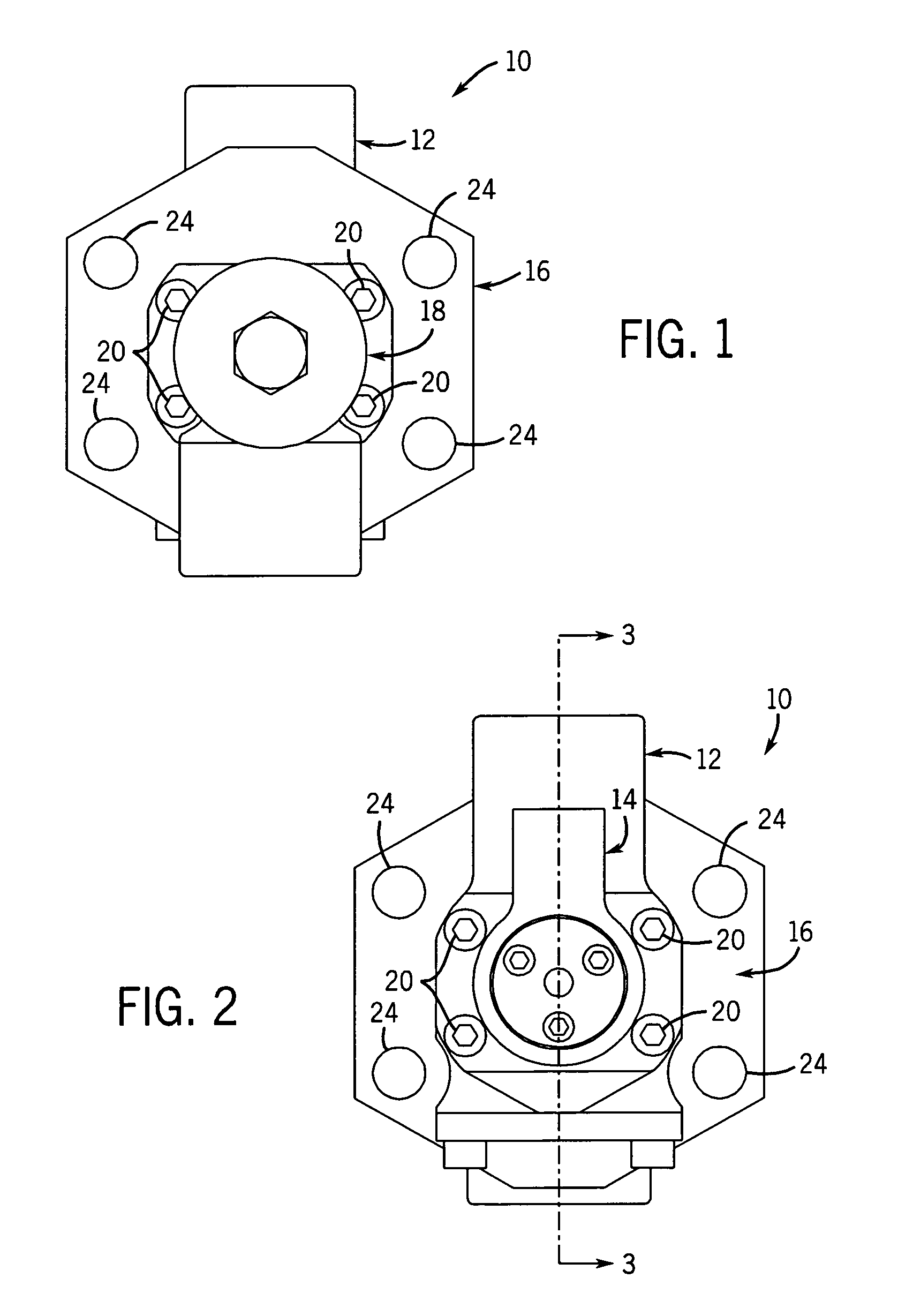
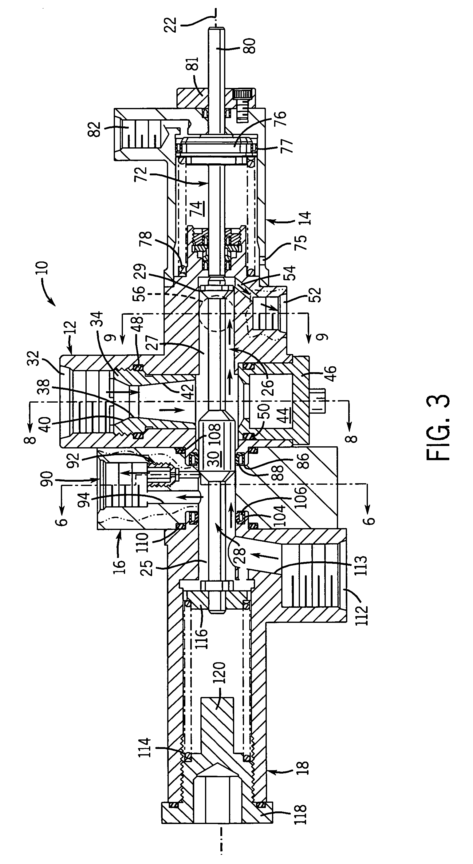
[0030]Referring now to FIGS. 1–3, a combination distributor purge valve unit 10 of the present invention is an assembly of a fuel section 12 with a pilot air section 14 mounted to one end and a distributor section 16 mounted to the opposite end to which is mounted a purge air section 18. These sectional components are assembled by bolts 20 to lie along a spool axis 22. The valve is preferably mounted to a combustion can (not shown) of a gas turbine engine (not shown) via rods (not shown) disposed through four mounting openings 24 in the distributor section 16. The use of rods minimizes the contact of the valve 10 with the combustion can, thereby reducing thermal conduction and the associated adverse effects, particularly coking.

[0031]Referring to FIG. 3, the fuel section 12, distributor section 16 and purge air section 18 define a central spool chamber 26, having an air only area 25 and a fuel only area 27, concentric with the spool axis 22 in which an elongated spool member 28 is d...


PUM


Abstract

A combination distributor purge valve unit for a turbine engine has a pilot air section, a fuel section, a distributor section and a purge air section. A spool moves along a spool axis to control flow through six sets of radially arranged removable fill nozzles and fixed outlet orifices in the distributor section. The spool moves from its initial position in which the distributor outlets are in communication with the inlet to the purge air section and closed off from the inlet to the fuel section so that high temperature purge air can forced passed the downstream side of the spool and into the nozzles in the combustion can of the turbine engine to eliminate coking in these areas. The spool moves against a biasing spring under the force of a pilot air driven actuator piston and the force of the pressurized fuel so that fuel can flow, initially through the fill nozzles and then the outlet orifices, to the combustion can.

Description

CROSS-REFERENCE TO RELATED APPLICATION[0001]This application claims benefit to U.S. provisional application Ser. No. 60 / 389,827 filed Jun. 18, 2002.STATEMENT OF FEDERALLY SPONSORED RESEARCH OR DEVELOPMENT[0002]Not applicable.BACKGROUND OF THE INVENTION[0003]1. Technical Field[0004]The present invention relates to valves, and in particular, to valves for use with turbine engines.[0005]2. Description of the Related Art[0006]Gas turbine engines employ a set of rotating turbine blades to compress air leading to a combustion can into which fuel is injected and ignited. Fuel is delivered through metering orifices to burners in the combustion chamber under pressure through a fuel line. Combustion of the fuel in the combustion can turns a downstream set of blades from which energy is extracted and which can also be used to drive the compressor blades.[0007]Many gas turbine engines are operable in liquid fuel (such as diesel fuel) and gaseous fuel (such as natural gas) modes. When the engine...

Claims


Application Information

Patent Timeline
Patent Type & Authority Patents(United States)
IPC IPC(8): F01D25/08F01D25/12F02C7/22F02C7/232F16K49/00
CPCF01D25/12F02C7/232F16K49/005F05D2260/602F05D2260/232Y10T137/86879Y10T137/4259
Inventor JANSEN, HARVEY B.
Owner JANSENS AIRCRAFT SYST CONTROLS
Why Eureka
Try Eureka