Free piston engine

a free-piston engine and piston technology, applied in the direction of engines without rotary main shafts, couplings, mechanical devices, etc., can solve the problem of relatively high device technology expenditure, and achieve the effect of reducing the production cost of free-piston engines and reducing expenditur

Inactive Publication Date: 2005-08-23
BOSCH REXROTH AG
View PDF8 Cites 23 Cited by
  • Summary
  • Abstract
  • Description
  • Claims
  • Application Information

AI Technical Summary

Benefits of technology

[0010]The free-piston engine of the invention has a stepped piston having a larger end face thereof guided in the compression cylinder, and a smaller end face in the work cylinder. Both the work cylinder and the compression cylinder may be connected with a common high-pressure accumulator for initiating the compression stroke or for charging during the expansion stroke. In comparison with the INNAS free-piston engine described at the outset, this variant has the advantage of mere...

Problems solved by technology

This INNAS free-piston engine has a substantially more complex structure in comparison with t...

Method used


Image

  • Free piston engine
  • Free piston engine
  • Free piston engine

Examples


Embodiment Construction

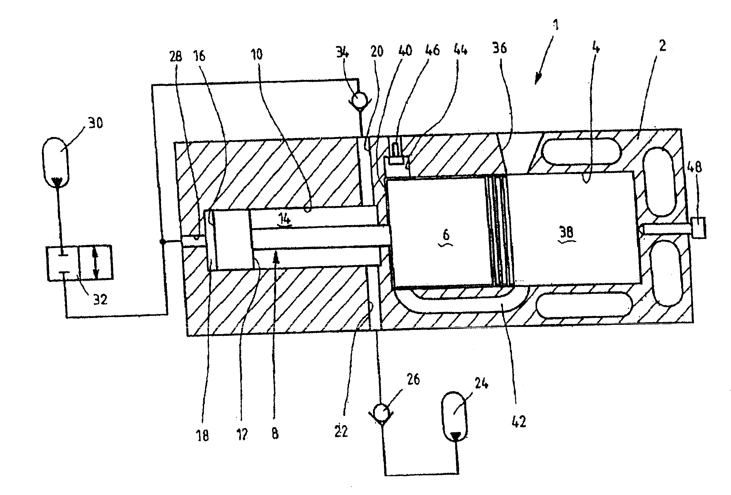
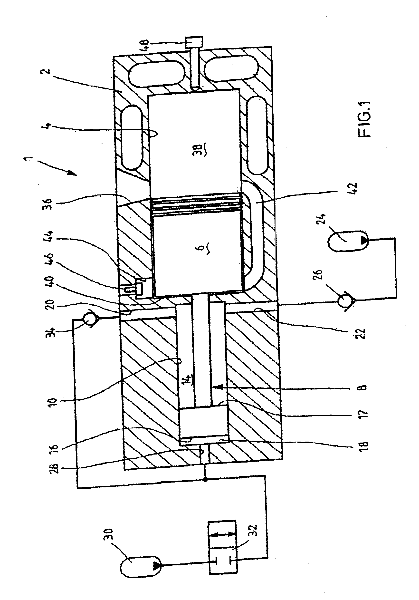
[0039]FIG. 1 shows a schematic representation of a first practical example of a free-piston engine 1. It has an engine housing 2, in the combustion cylinder 4 of which an engine piston 6 is guided. The latter is in operative connection with a coaxially arranged hydraulic piston 8 guided in an axial bore 10. An annular end face 12 of the hydraulic piston 8 defines a work cylinder 14, while the larger end face 16 of the hydraulic piston 8 defines a compression cylinder 18.

[0040]A pressure passage 20 and a low-pressure passage 22 merge into work cylinder 14. The low-pressure passage is connected with a low-pressure accumulator 24 wherein a pressure medium flow from work cylinder 14 to low-pressure accumulator 24 is prevented by a check valve 26.

[0041]Compression cylinder 18 is connected with a high-pressure accumulator 30 via a high-pressure passage 28 wherein the high-pressure passage 28 may be controlled open and closed with the aid of a starting valve 32 designed as a 2 / 2-way direct...


PUM


Abstract

A free-piston engine has a stepped piston having a larger end face thereof guided in the compression cylinder, and a smaller end face in the work cylinder. Both the work cylinder and the compression cylinder are connected with a common high-pressure accumulator for initiating the compression stroke or for charging during the expansion stroke.

Description

BACKGROUND OF THE INVENTION[0001]1. Field of the Invention[0002]The invention relates to a free-piston engine.[0003]2. Description of the Related Art[0004]A free-piston engine fundamentally is a combustion engine working according to the 2-cycle method and having not a crankshaft drive but a hydraulic circuit including a reciprocating pump as its subsequently arranged drive train. To this end, the engine piston is connected to a hydraulic cylinder whereby the translatory energy generated during a work cycle of the engine is supplied directly to the hydraulic work medium, without the classical by-way of the rotary movement of a crankshaft drive. The subsequently arranged, storage-capability hydraulic circuit is designed such as to absorb the output power and buffer it for supplying it to a hydraulic output unit, e.g., an axial piston engine, in accordance with power demand.[0005]In DE 40 24 591 A1 a free-piston engine of the generic type is described, also known as a Brandl free-pist...

Claims


Application Information

Patent Timeline
IPC IPC(8): F02B71/00F02B71/04F01B11/08F01B23/08
CPCF02B71/045
Inventor SCHAEFFER, RUDOLF
Owner BOSCH REXROTH AG
Why Eureka
Try Eureka