Stirling engine having platelet heat exchanging elements

a technology of heat exchange elements and rotating engines, which is applied in the direction of machines/engines, laminated elements, light and heating apparatus, etc., can solve the problems of inefficiency of rotating engines, heat is often not evenly distributed to the working gas within the heater tube, and achieves the effect of running more efficiently

Inactive Publication Date: 2005-08-23
DISENCO +1
View PDF6 Cites 59 Cited by
  • Summary
  • Abstract
  • Description
  • Claims
  • Application Information

AI Technical Summary

Benefits of technology

[0010]The present invention is directed to a heat exchange manifold for use in a Stirling engine. According to the present invention, the heat exchange manifold is provided using a platelet construction. More specifically, the heat exchange manifold is formed of multiple platelets that are stacked and joined together. A platelet device is a device, which is designed to control and manage fluid flow and is constructed of individual layers (called platelets). The platelet construction of the heat exchange manifold provides integrated fluid management (IFM), which advantageously permits the Stirling engine to run more efficient because the heat exchange and combustion process are improved.
[0012]This platelet construction advantageously permits precision fabrication of the conduits and combustion chamber in the manifold. This results in more efficient heat transfer to the working gas as the overall size of each individual combustion chamber and each working gas circuit is substantially reduced in comparison with conventional manifolds due to the design of the present invention. More specifically, instead of having one large burner device with one combustion chamber and 36 or so working gas circuits (heater tubes) per piston cylinder, the manifold of the present invention has a substantially greater number of individual combustion chambers, e.g., over 100 and preferably over 200 per piston cylinder, as well as over 100 hundred working gas circuits. As a result, the dimensions of each combustion chamber and each working gas circuit are substantially reduced and may be precisely tailored using platelet technology. This results in a reduction of dead volume in each working gas circuit, improved heat transfer from the combustion chamber to the working gas, and improved efficiency of the combustion process performed in the combustion chamber.
[0013]In another aspect of the present invention, platelet technology is used to incorporate the internal region of the Stirling displacer cylinder head end into a platelet stack, which provides multiple heat exchangers. In a first aspect, the cylinder head end has working gas channels and ports formed therein to permit the working gas to flow to and from the cylinder head end region. By forming the working gas channels in the head end, an even more effective and efficient heat transfer surface area is provided and this results in a more compact and lighter weight Stirling engine. In another aspect, the present invention provides an integrated structure in which all of the major parts of the head end of the Stirling cycle engine are integrated into one cylindrical platelet device. The use of very small platelet coolant passageways makes possible small, yet highly efficient heat exchangers. In other words and according to one embodiment, channeled platelet members are annularly arranged to form a piston chamber and also provide all of the heat exchangers for the head end.
[0014]In yet another aspect of the present invention, a multi-stage combustor for use in the Stirling engine is provided and may or may not include inter-stage cooling. The combustors of the present invention are able to reduce the emission of NOx by having a first combustor which operates at fuel rich or stoiochiometric conditions (low NOx emission) and a second combustor which introduces secondary air to dilute the combustion gases and reduce the combustion temperature while maintaining the NOx emission at low levels. High system performance is still maintained.
[0015]In yet another embodiment, the head end of the Stirling engine includes a working gas heat exchanging plate which is bonded on top of a platelet manifold which is itself coupled to the head end of the piston cylinder. The platelet manifold includes a number of channels, which receive the working gas and serve to both distribute the working gas to the heat exchanging plate and also provide communication ports to the piston chamber, so that the working gas may flow into and out of the piston chamber. The heat exchanging plate has a number of heat transfer passageways to efficiently heat the working gas and to provide metal cooling capability. The heat exchanging plate is in fluid communication with the platelet manifold so that the heated working gas flows into and out of the channels of the manifold. The working gas is heated as it flows through the plate because one surface of the plate is in direct contact with the hot combustion gases formed during the combustion process and actually, the plate partially forms the combustion chamber.
[0016]A platelet air injector is provided and is a platelet manifold for unburned combustion air and acts to simultaneously cool the air manifold platelets and preheat the incoming combustion air. The platelet air injector has a number of swirler orifices formed therein for injecting air into the hot combustion gases as they flow from the combustion chamber. The air is aimed at an upper surface of the heat exchanging plate to enhance combustion mixing and aid in the heat transfer between the hot combustion gases and the plate. This embodiment utilizes multi-staged micro-combustion for burning the fuel rich gas to completion resulting in many advantages described hereinafter.

Problems solved by technology

One of the disadvantages of current Stirling engines is their inefficiency due to the presence of dead volume of a working gas and the overall volumetric size of a burner device of the heat exchanging assembly.
Because a single burner device is used to generate and effectuate heat transfer to the working gas flowing within a number of heater tubes, heat is often not evenly distributed to the working gas within the heater tubes.
The associated disadvantage of such a system is that conventional heater tubes usually contain a dead volume of working gas.
This results in inefficient heat transfer from the burner device to the working gas and in turn leads to inefficient operation of the Stirling engine itself.
In addition, due to the typical size of the burner device, the burner device first heats a significant volume of air before heat transfer occurs to the working gas.
This results in a considerable amount of energy being consumed before the working gas is heated and as a result, the working gas is exposed to less heat due to the inefficiencies of the burner device.

Method used


Image

  • Stirling engine having platelet heat exchanging elements
  • Stirling engine having platelet heat exchanging elements
  • Stirling engine having platelet heat exchanging elements

Examples


second embodiment

[0085]Referring now to FIGS. 8-15, a heat transfer manifold is shown and indicated at 400. The heat transfer manifold 400 is similar to the heat transfer manifold 10 and therefore like elements are numbered alike.

[0086]The heat transfer manifold 400 includes a platelet structure 410 defined by the air / fuel intake platelet zone 210, the air preheat platelet zone 220, the air / fuel mixing platelet zone 230, the combustion platelet zone 240, and the working gas expansion / compression platelet zone 250. In this embodiment, the combustion platelet zone 240 is actually formed by first, second, third, and fourth combustion platelet zones 242, 244, 246, 248, respectively. In addition, the working gas expansion / compression platelet zone 250 is defined by first, second, third, and fourth platelet zones 252, 254, 256, and 258.

[0087]Like the platelet structure 200, the stack of platelets 410 are joined together to form a single monolithic structure. The stack of platelets 410 has a shape which i...
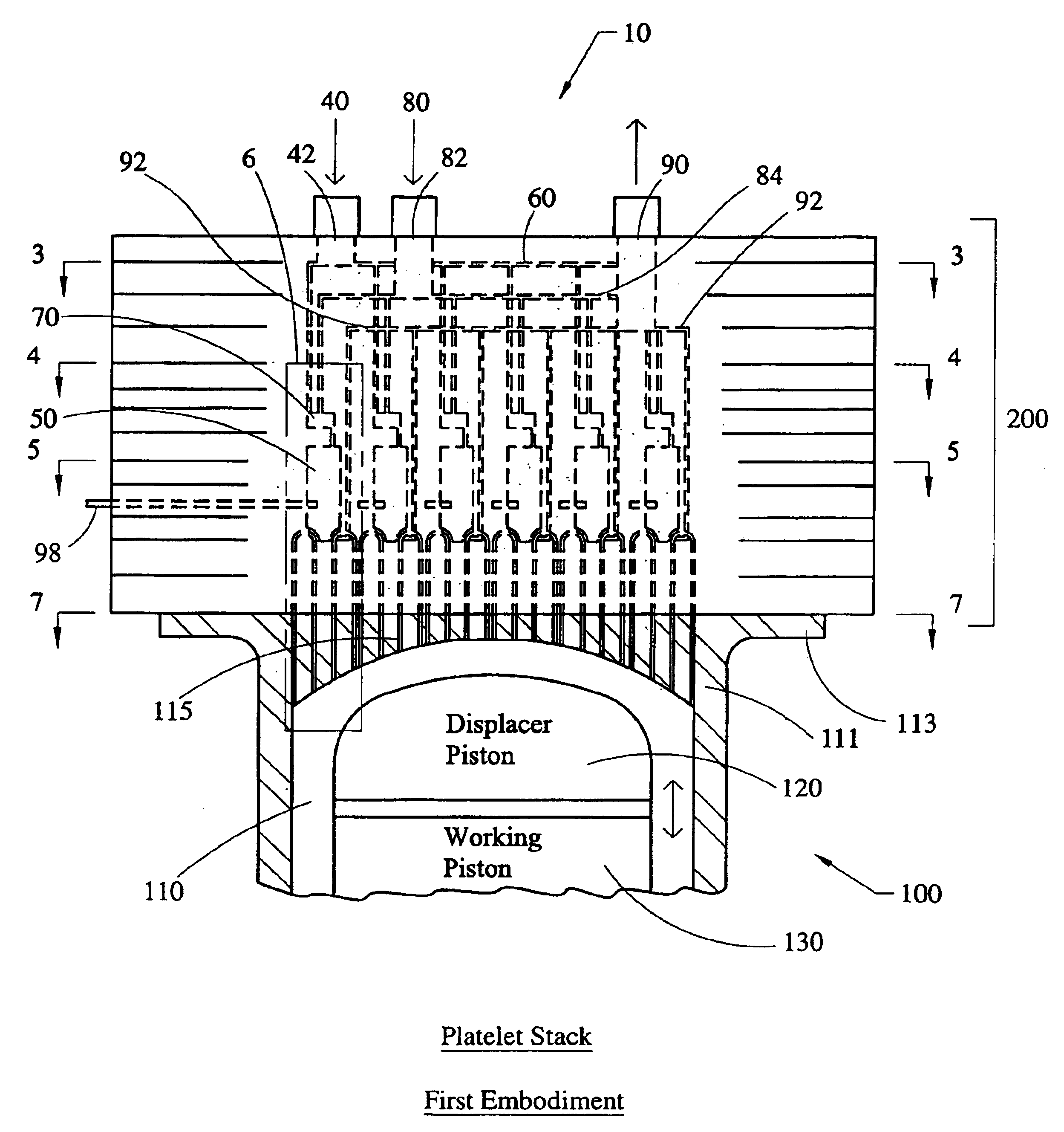
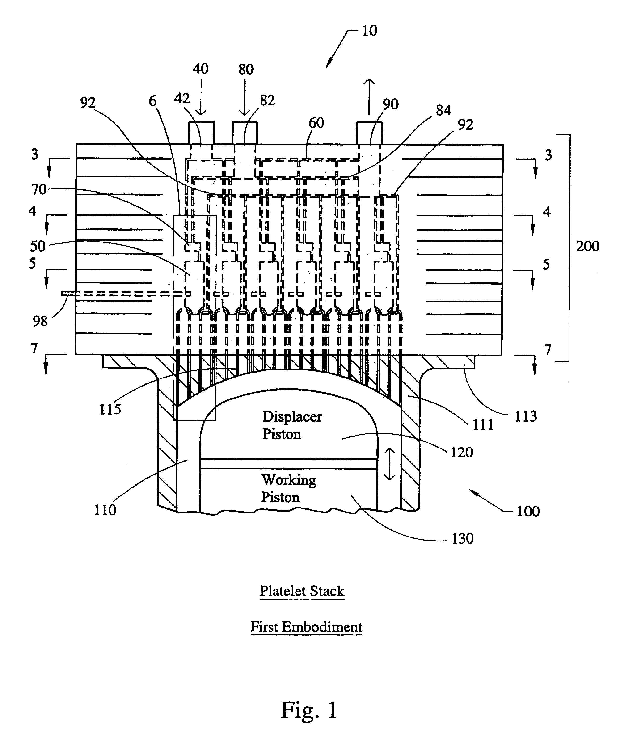
first embodiment

[0134]In the multi-stage combustor system 1000, shown in FIG. 24, a two-stage combustion process without inter-stage cooling is presented. FIG. 24 illustrates generally the heat exchange components of the multi-stage combustor system 1000. The heat exchange components of the multi-stage combustor system 1000 include the first section 760 and the second section 770 (regenerator). The third section 780 (FIG. 16) is not present in this embodiment since this embodiment does not include inter-stage cooling. The first section 760 has a plurality of working gas channels 800 which extend into the second section 770 and also includes a plurality of the combustion gas channels 810.

[0135]The multi-stage combustor system 1000 includes a first (primary) combustor 1010 and a second (secondary) combustor 1020. The first combustor 1010 is coupled to a fuel injection / ignition device 1030. The device 1030 includes a number of fuel channels 1032 and air channels 1034, which serve to provide fuel and a...


PUM


Abstract

The present invention provides heat exchanging elements for use in Stirling engines. According to the present invention, the heat exchanging elements are made from muliple platelets that are stacked and joined together. The use of platelets to make heat exchanging elements permits Stirling engines to run more effiecient because the heat transfer and combustion processes are improved. In one embodiment, multi-stage combustion can be introduced with platlets, along with the flexibility to use different types of fuels. In another embodiment, a single component constructed from platelets can provide the heat transfer rquirements betweeen the combustion gas / working gas, working gas in the regenerator and the working gas / coolant fluid of a Stirling engine. In another embodiment, the platelet heat exchanging element can recieve solar energy to heat the Stirling engine's working gas. Also, this invention provides a heat exchanging method that allows for multiple fluids to flow in opposing or same direction.

Description

[0001]This application is a continuation of Ser. No. 10 / 090,673 filed Mar. 4, 2002 now U.S. Pat. No. 6,513,326, which claims benefit of provision of 60 / 273,424 filed Mar. 5, 2001 and claims benefit of provision 60 / 309,749 filed Aug. 2, 2001.FIELD OF THE INVENTION[0002]The present invention relates to Stirling engines and more particularly to heat exchanging elements thereof which are formed of platelets.BACKGROUND OF INVENTION[0003]The basic concept of the Stirling engine dates back to the developments of Robert Stirling in 1817. Over the years, numerous applications for the Stirling engine have been investigated and evaluated. For example, one potential use of the Stirling engine is in automobiles and the like as a prime mover. In addition, the Stirling engine may be used as an engine power unit for hybrid electric applications. Other potential applications are the use of the Stirling engine as an auxiliary power unit and the use of the Stirling engine in marine applications and so...

Claims


Application Information

Patent Timeline
Patent Type & Authority Patents(United States)
IPC IPC(8): F02G1/00F02G1/055F02G1/043F28F3/00F28F3/12F24J2/06F24J2/07F28F9/18F28F9/04F28F3/04F28D9/00F24S20/20
CPCF02G1/043F02G1/055F24J2/07F28D9/0018F28D9/0025F28D9/0037F28D9/0093F28F3/04F28F3/048F28F3/12F28F9/18F28F2275/04Y02E10/41F28F2250/102F28F2250/104F24S20/20Y02E10/40
Inventor MACEDA, JOSEPH P.PEETERS, RANDALL L.CHEN, FELIX F.HEWITT, ROSS A.ITO, JACKSON I.KLAAS, KENNETH P.GRIMES, JOHN L.HESTEVIK, SVEIN
Owner DISENCO
Why Eureka
Try Eureka