Boosted air source heat pump

a heat pump and air source technology, applied in the field of air source heat pumps, can solve the problems of inefficient power consumption, insufficient capacity etc., and achieve the effect of eliminating unnecessary, unsafe and/or inefficient system operation, and preventing unnecessary and/or inefficient microprocessor operation

Inactive Publication Date: 2005-08-23
NORTHEAST BANK
View PDF51 Cites 26 Cited by
  • Summary
  • Abstract
  • Description
  • Claims
  • Application Information

AI Technical Summary

Benefits of technology

[0005]Heating and cooling system control is achieved with a multi-step indoor thermostat employed in conjunction with a refrigerant system low side pressure sensor that is commensurate with outdoor ambient temperature. The multi-step thermostat has settings that call for various steps of heating or cooling operation; and the low side pressure sensor operates to prevent unnecessary, unsafe and / or inefficient operation of the system. The complication and expense of a microprocessor can be eliminated.
[0006]The present invention also includes a circulating defrost energy transfer fluid system (as defined herein) for a defrost cycle for the heat pump mode of operation. Instead of having to use resistance heating while pulling heat out of the heated indoor air for the defrost cycle, the present invention utilizes a defrost energy transfer fluid for heat exchange to add thermal energy to vaporize the circulating refrigerant to effect the defrost operation. This eliminates the necessity of using electric resistance heating, thereby avoiding cold drafts during the defrost cycle.

Problems solved by technology

Heat pumps that are designed to deliver sufficient capacity at very cold outdoor temperatures may have the inherent problem of delivering too much capacity when the outdoor temperature warms up, because more energy is available to be obtained from the warmer outdoor air.
This may cause system inefficiencies as the system heat exchangers become overloaded and compressor power consumption rises to inefficient levels.
In extreme cases, safety controls may cause the compressor to stop running.

Method used


Image

  • Boosted air source heat pump
  • Boosted air source heat pump
  • Boosted air source heat pump

Examples


Embodiment Construction

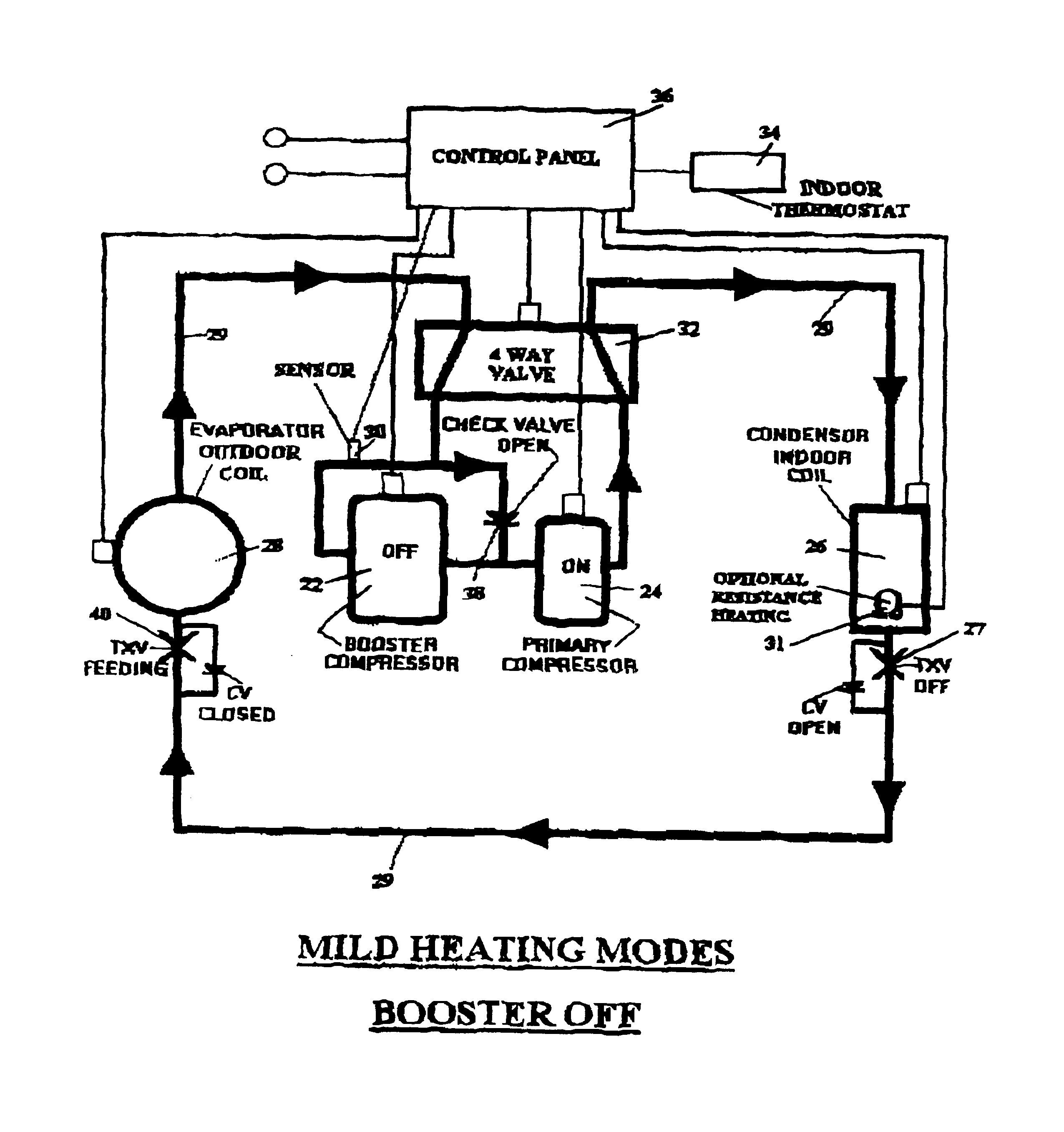
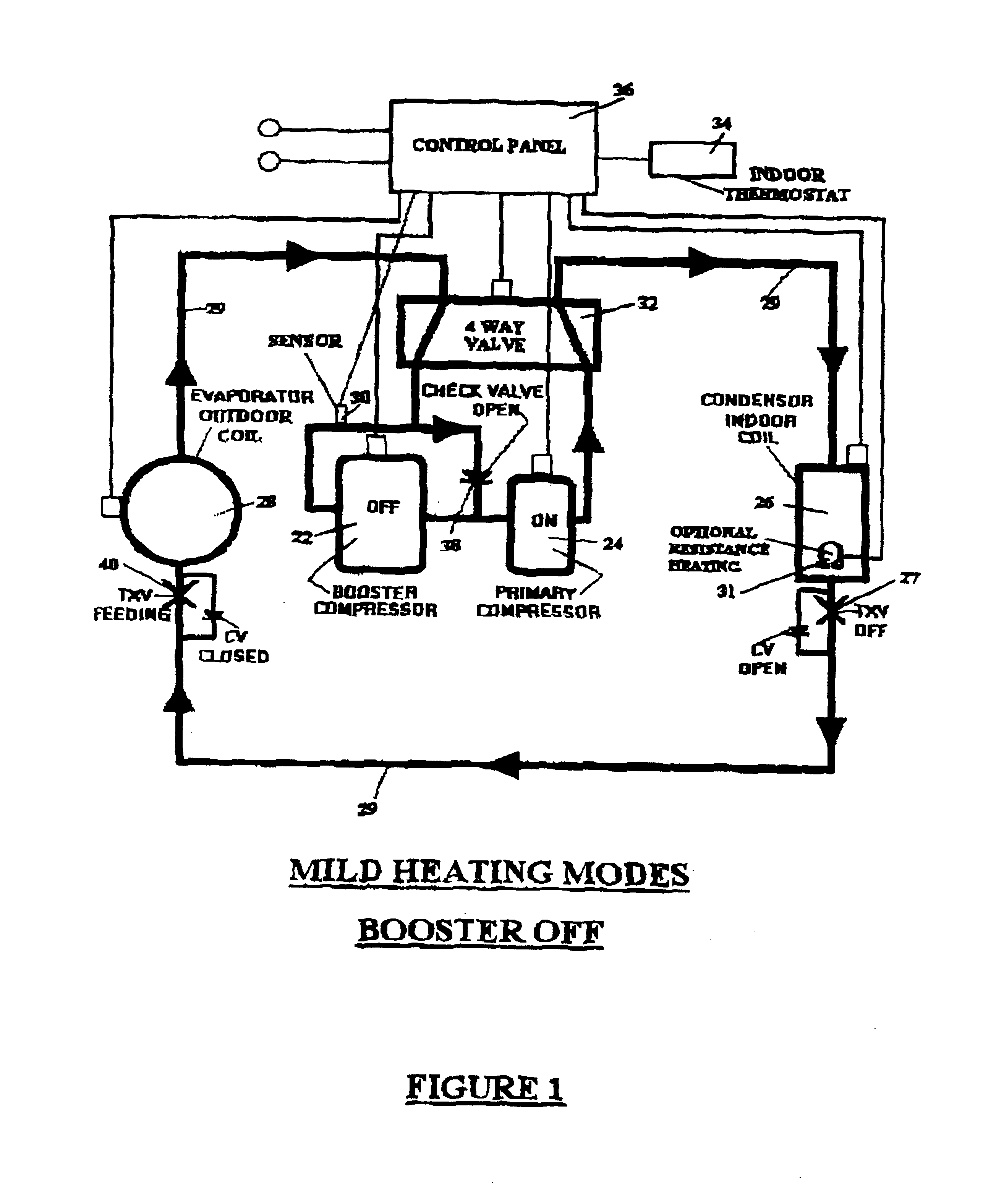
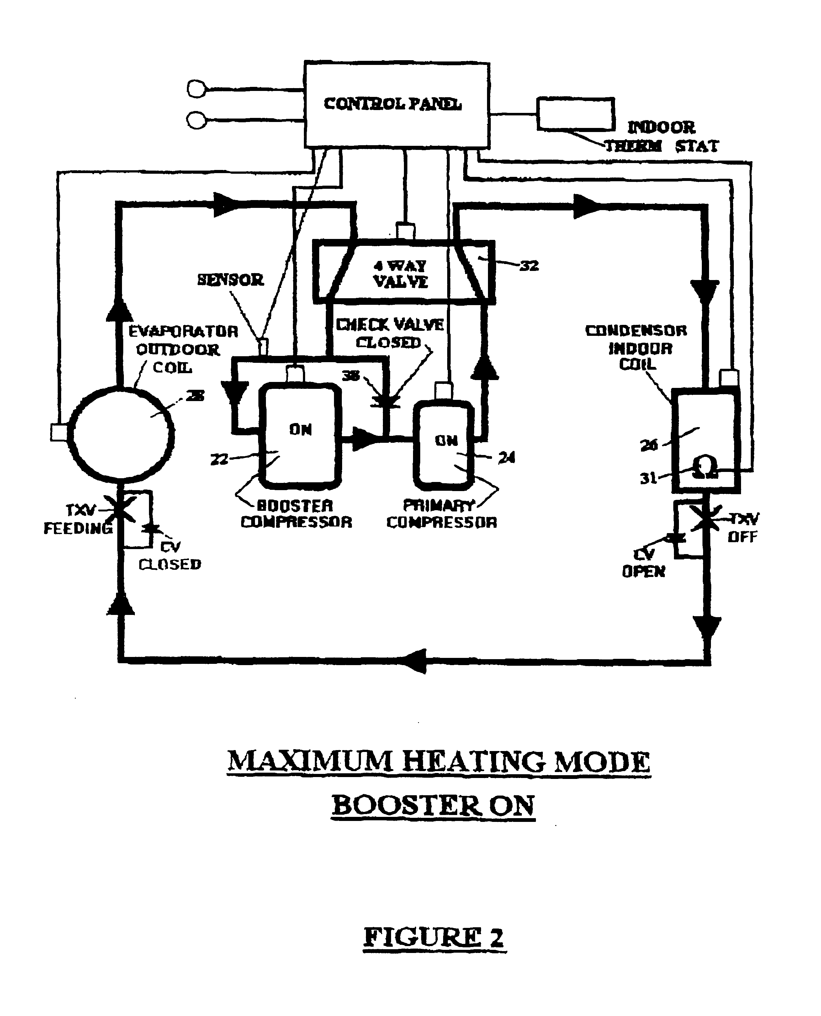
[0015]Referring to FIGS. 1, 2 and 3, a closed loop heat pump system is shown. The system has a booster stage compressor 22, a primary compressor 24, an indoor coil or condenser 26 which delivers heat to a space to be heated, an outdoor coil or evaporator 28, and conduit means 29 connecting these elements in a closed loop circuit. The system also has a refrigerant system pressure sensor 30, the output of which is commensurate with outdoor ambient air temperature. Pressure sensor 30 is located in a position so that it is always exposed to the refrigerant low pressure side of the system. The heat pump system also has a four way valve 32 to reverse the direction of refrigerant flow when the system switches from the heating mode to the cooling mode, and vice-versa; an indoor thermostat 34 to select and sense the temperature of the air in the space to be heated (or cooled); and a control panel / mini-microprocessor 36 for receiving signals from the thermostat and pressure sensor 30 and for ...


PUM


Abstract

A heat pump system is presented having a primary compressor, a booster compressor, a multi-step thermostat, an indoor coil, an outdoor coil, a refrigerant flow conduit connecting these elements is a closed loop system, and at least one pressure sensor positioned to always sense the refrigerant system low side pressure, which is commensurate with outdoor ambient air temperature in all heating modes of operation. The pressure sensor functions as an override and safety control to prevent or permit operation of the compressors, and also other system components, depending on outside air temperature. The primary compressor is preferably a multi-capacity compressor. A defrost energy transfer fluid is used in a defrost cycle.

Description

BACKGROUND[0001]This invention relates to air source heat pumps, and especially to air source heat pumps suitable for use in normally colder climates. This invention is a modification and improvement to the inventions in prior U.S. Pat. Nos. 6,276,148 and 5,927,088 in that this invention presents a somewhat simpler and less expensive air source heat pump system. The entire contents of my prior U.S. Pat. Nos. 6,276,148 and 5,927,088 are incorporated herein by reference.[0002]Heat pump capacity is understood in the art to be the amount of heat per unit time delivered by a heat pump system. An effective heat pump system must deliver adequate capacity with low or falling outdoor temperature, while avoiding the delivery of too much capacity when the outdoor temperature warms up. Heat pumps that are designed to deliver sufficient capacity at very cold outdoor temperatures may have the inherent problem of delivering too much capacity when the outdoor temperature warms up, because more ener...

Claims


Application Information

Patent Timeline
Patent Type & Authority Patents(United States)
IPC IPC(8): F25B1/10F25B13/00F25B49/02F25B47/02
CPCF25B1/10F25B13/00F25B47/025F25B49/022F25B2313/0211F25B2400/0401F25B2400/13F25B2600/022F25B2600/0251F25B2600/0253F25B2700/1933F25B2700/2106F25D2700/12Y02B30/741Y02B30/70
Inventor SHAW, DAVID N.FISHMAN, DAVID S.
Owner NORTHEAST BANK
Why Eureka
Try Eureka