
Tuning fork vibration gyro

a vibration gyro and tuning fork technology, applied in the direction of calibration apparatus, turn-sensitive devices, instruments, etc., can solve the problems of deteriorating signal-to-noise ratio of tuning fork type vibration gyro, increasing production costs, and reducing reproducibility, so as to suppress parasitic vibration induced and accurately trim the imbalance of detecting electrode areas

Inactive Publication Date: 2005-08-23
TAMAGAWA SEIKI CO LTD
View PDF13 Cites 11 Cited by
  • Summary
  • Abstract
  • Description
  • Claims
  • Application Information

AI Technical Summary

Benefits of technology

[0022]Accordingly, it is an object of the present invention to provide a tuning-fork type vibration gyro and an electrode trimming method therefor, enabling to suppress pyroelectric noise caused by temperature change and to obtain sensor output having high signal-to-noise ratio.
[0025]According to the present invention, the dummy electrodes on the surface of the arms enable to average the surface potential of the ferroelectric body, thus eliminating high potential portion. Therefore, even when temperature change produces excessive amount of charges, dielectric breakdown on the surface of the ferroelectric body can be avoided. Thus generation of pyroelectric noise can be suppressed and the tuning-fork type vibration gyro having high signal-to-noise ratio can be obtained.
[0027]According to the invention, because the driving electrodes and the detecting electrodes are disposed in mutually deviating positions against z-axis, it is possible to prevent misidentification of a driving electrode against a detecting electrode during the electrode trimming process in manufacturing of the tuning-fork type vibration gyro.
[0029]According to the invention, pyroelectric noise input to the differential amplifier can be reduced by a capacitor or other voltage limiting element connected to the input or other voltage limiting element connected to the input terminals of the differential amplifier. This enables to improve signal-to-noise ratio of the tuning-fork type vibration gyro.
[0031]According to the invention, a transistor in the first stage of the differential amplifier is separated from transistors in the succeeding stages. This can prevent pyroelectric noise from transmitting to the succeeding stages, enabling to improve signal-to-noise ratio of the tuning-fork type vibration gyro.
[0033]According to the invention, because the vibration of support substrate is suppressed, thus suppressing the parasitic vibration induced to the arms, only leak Ax resulting from the vibration parallel with x-axis (i.e. fx mode vibration) can be extracted. This enables to trim the imbalance of detecting electrode areas accurately.

Problems solved by technology

In this case, when charges of reverse polarity are combined abruptly, pyroelectric noise is produced resulting in signal-to-noise ratio deterioration of the tuning-fork type vibration gyro.
This may well bring about increasing production cost.
Furthermore, affected by surrounding humidity, the resistance value of high resistance film 97 may deviate, which degrades reproducibility.

Method used


Image

  • Tuning fork vibration gyro
  • Tuning fork vibration gyro
  • Tuning fork vibration gyro

Examples


Embodiment Construction

[0055]The preferred embodiments of the present invention are described hereinafter referring to the charts and drawings.

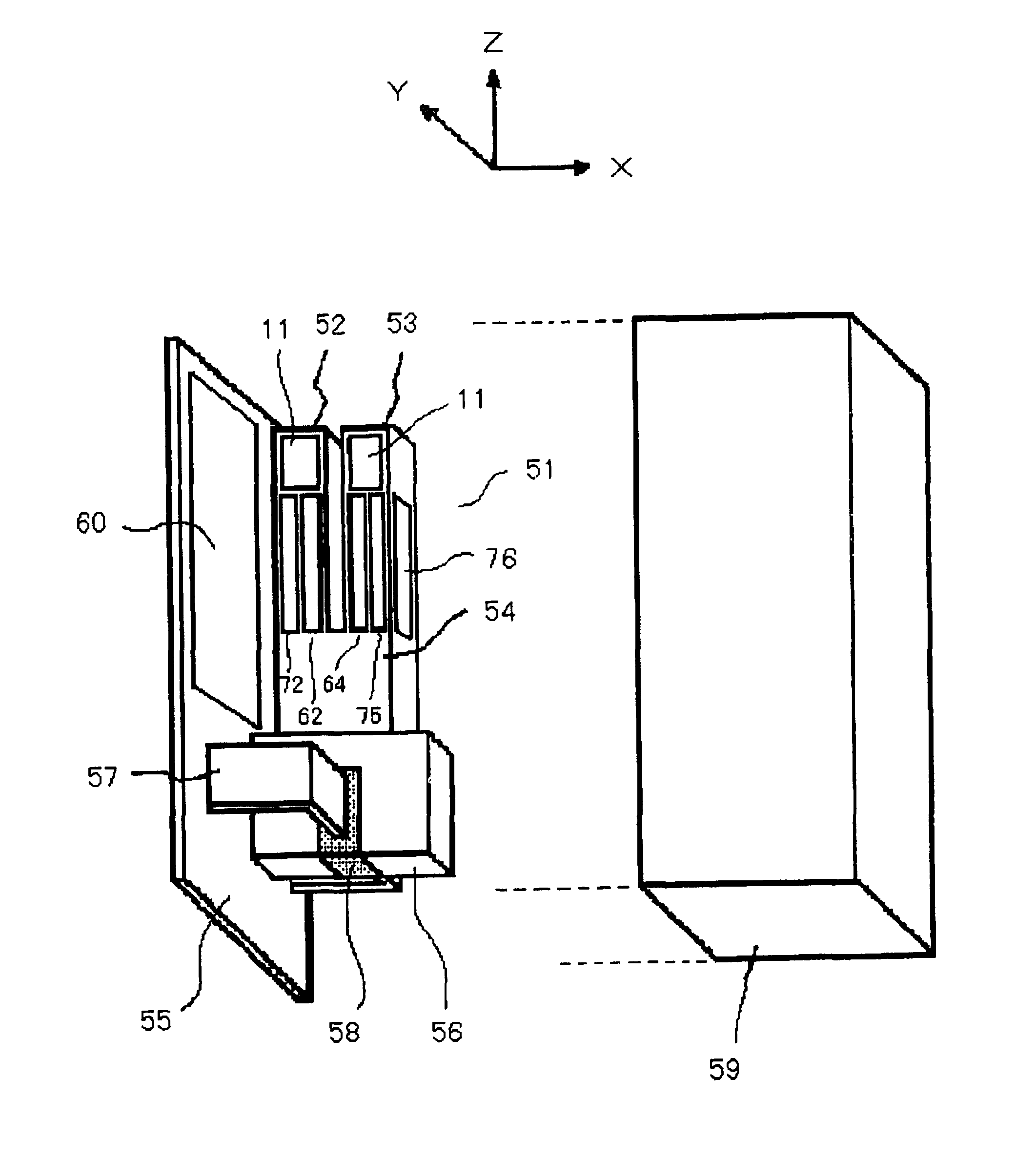
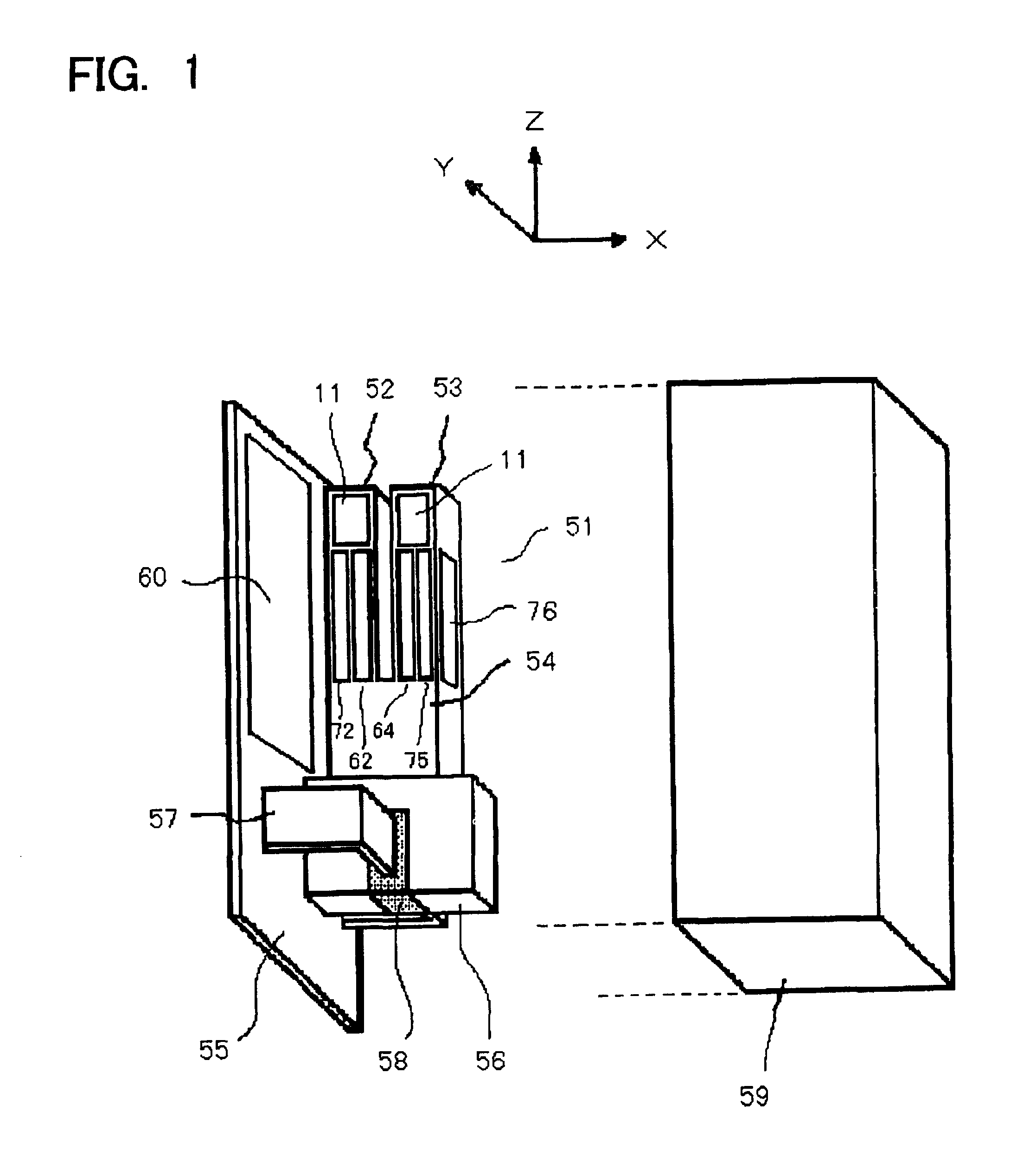
[0056]FIG. 1 shows a schematic configuration diagram of a tuning-fork type vibration gyro according to an embodiment of the present invention. The tuning-fork type vibration gyro is provided with tuning-fork type vibration body 51 integrally formed of ferroelectric body such as lithium tantalate (LiTaO3), lithium niobate (LiNbO3), or the like. In tuning-fork type vibration body 51, there are provided driving electrodes 62, 64, etc. and detecting electrodes 72, 75, 76, etc., as well as dummy electrodes 11 on the surface of two arms 52, 53 so as to reduce pyroelectric noise. Other configuration of the tuning-fork type vibration gyro is substantially the same as the conventional configuration shown in FIG. 15.

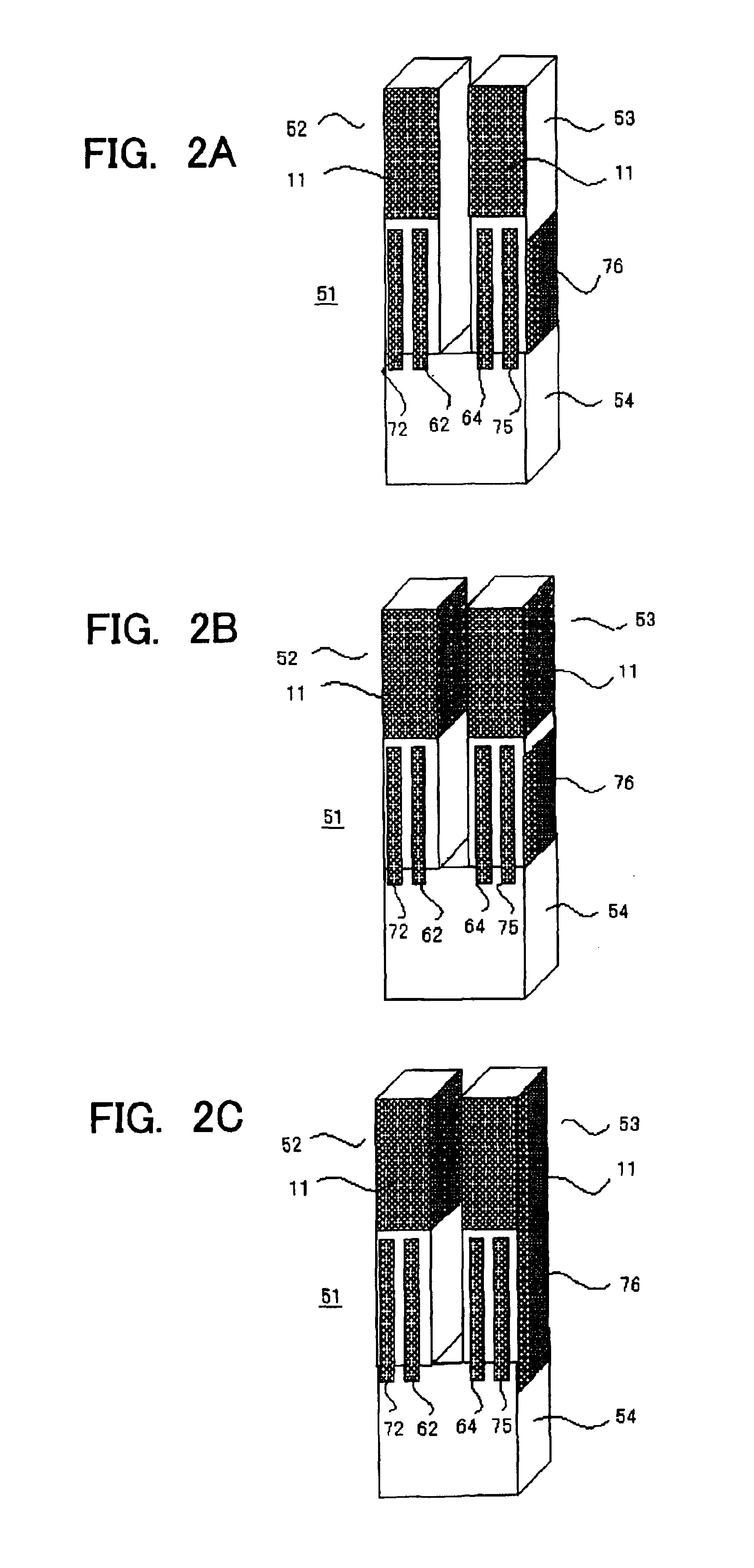
[0057]In FIGS. 2A through 2C, there are shown explanatory diagrams of an electrode configuration in tuning-fork type vibration body 51 according to an embodiment...


PUM


Abstract

A tuning-fork vibration gyro including a ferroelectric tuning-fork vibration body generating a plurality of sensor signals and a sensor circuit to which the sensor signals generated by the tuning-fork vibration body are input. The sensor circuit includes a differential amplifier having two input terminals between which the sensor signals are input, and a capacitor being connected between the two input terminals of the differential amplifier.

Description

[0001]This application is a division of application Ser. No. 09 / 930,147 filed Aug. 16, 2001 now U.S. Pat. No. 6,647,786.FIELD OF THE INVENTION[0002]The present invention relates to a tuning-fork type vibration gyro and an electrode trimming method therefor and more particularly a tuning-fork type vibration gyro and an electrode trimming method therefor which enable to reduce pyroelectric noise produced by temperature change and to obtain sensor output having high signal-to-noise ratio.BACKGROUND OF THE INVENTION[0003]In recent years, a tuning-fork type vibration gyro has been developed aiming to provide a miniaturized gyroscope. The gyro of this type typically includes two arms and a base to support the arms integrally formed of ferroelectric material. The gyro is used for detecting angular rate in a car navigation system, unintentional hand movement in a video camera, and so forth.[0004]In FIG. 15, there is shown a schematic configuration diagram of an example of the tuning-fork ty...

Claims


Application Information

Patent Timeline
Patent Type & Authority Patents(United States)
IPC IPC(8): G01C19/56G01C19/5607G01P1/04G01P21/00H01L41/09
CPCG01C19/5607
Inventor OHTA, KAZUHIROYACHI, MASANORITAKAHASHI, YOSHITAKAKIKUCHI, KAZUTSUGUSAITO, KEIJI
Owner TAMAGAWA SEIKI CO LTD
Learn More