Power generation system

a power generation system and wind power technology, applied in the direction of liquid fuel engines, marine propulsion, vessels, etc., can solve the problems of increasing the torque, creating inefficiencies, and reducing the efficiency of the power generator, so as to improve the size of the power generator and reduce the siz

Inactive Publication Date: 2005-08-23
WAFERMASTERS
View PDF6 Cites 39 Cited by
  • Summary
  • Abstract
  • Description
  • Claims
  • Application Information

AI Technical Summary

Benefits of technology

[0009]The present invention discloses a wind power generation system to operate in various wind conditions and with changing wind directions. The system provides a reliable and effective means for directing air currents into and out of fan generators positioned strategically within the power generation system.
[0011]Generally, the invention includes a wind capturing device that resembles a sail in performance. The wind capturing device effectively forces captured wind to form a high pressure area on a first side of at least one generator fan. The high pressure air travels across the generator fan to an area of lower pressure at a second side of the at least one generator fan.
[0012]Multiple wind power generation systems can be positioned together to form a large array of power generation systems which form a power unit. In this manner, a large expansive area can be exposed to the wind. As explained in detail below, since each power system in the array operates independent of the other power systems, the direction of wind impinging on the expansive array does not adversely affect the power output.

Problems solved by technology

Unfortunately, typical wind power systems require large propeller-like blades, which can be inefficient, to the point of being useless.
Inefficiencies are created due to considerable friction in the gear box, which adds to the torque.
Thus, during instances of low or moderate wind flow, the wind strength may not be able to overcome the torque.
Each of these factors contributes to the cost of the wind power system, operations, and maintenance, which add considerably to the cost of the power generated.

Method used


Image

  • Power generation system
  • Power generation system
  • Power generation system

Examples


Embodiment Construction

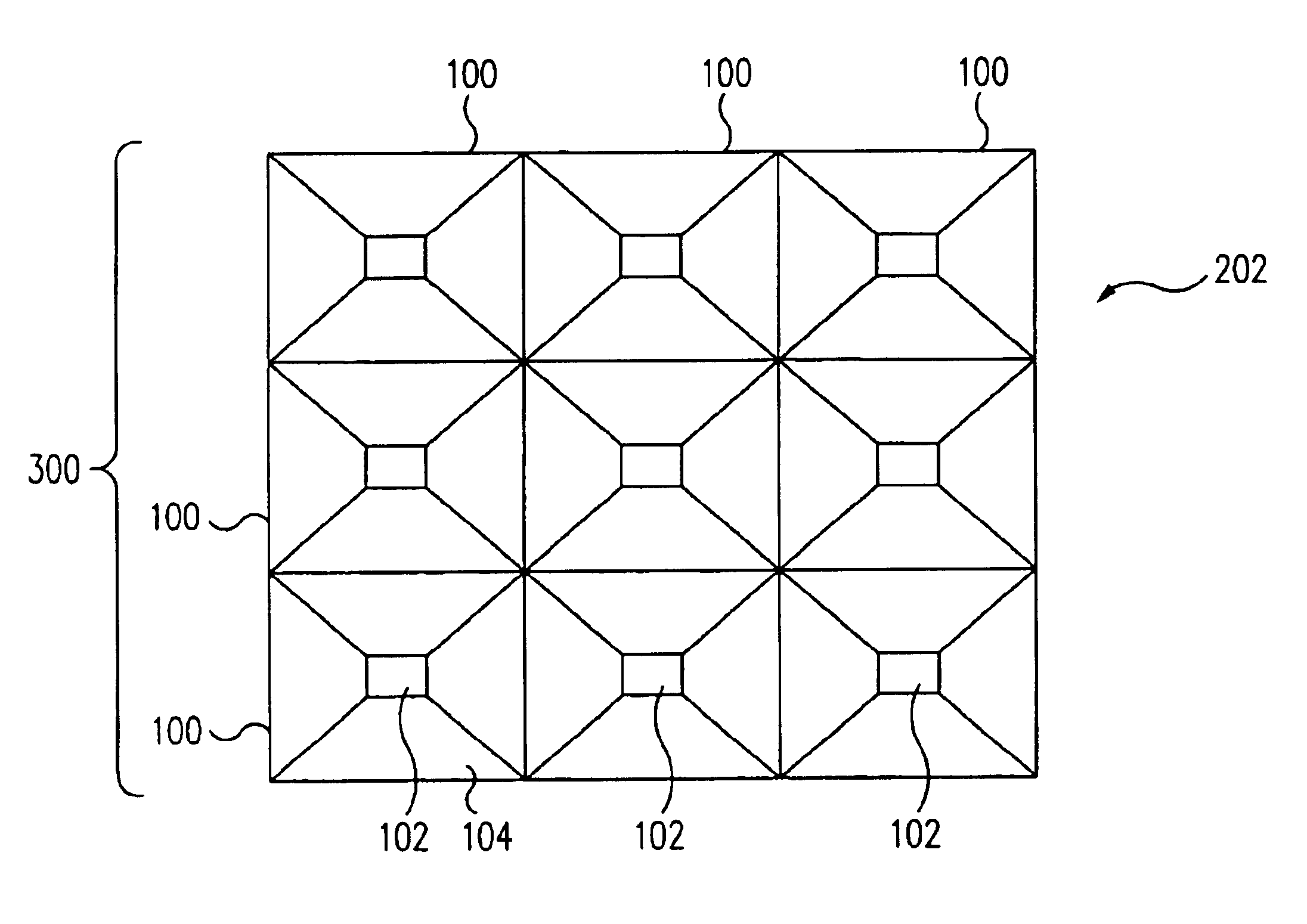
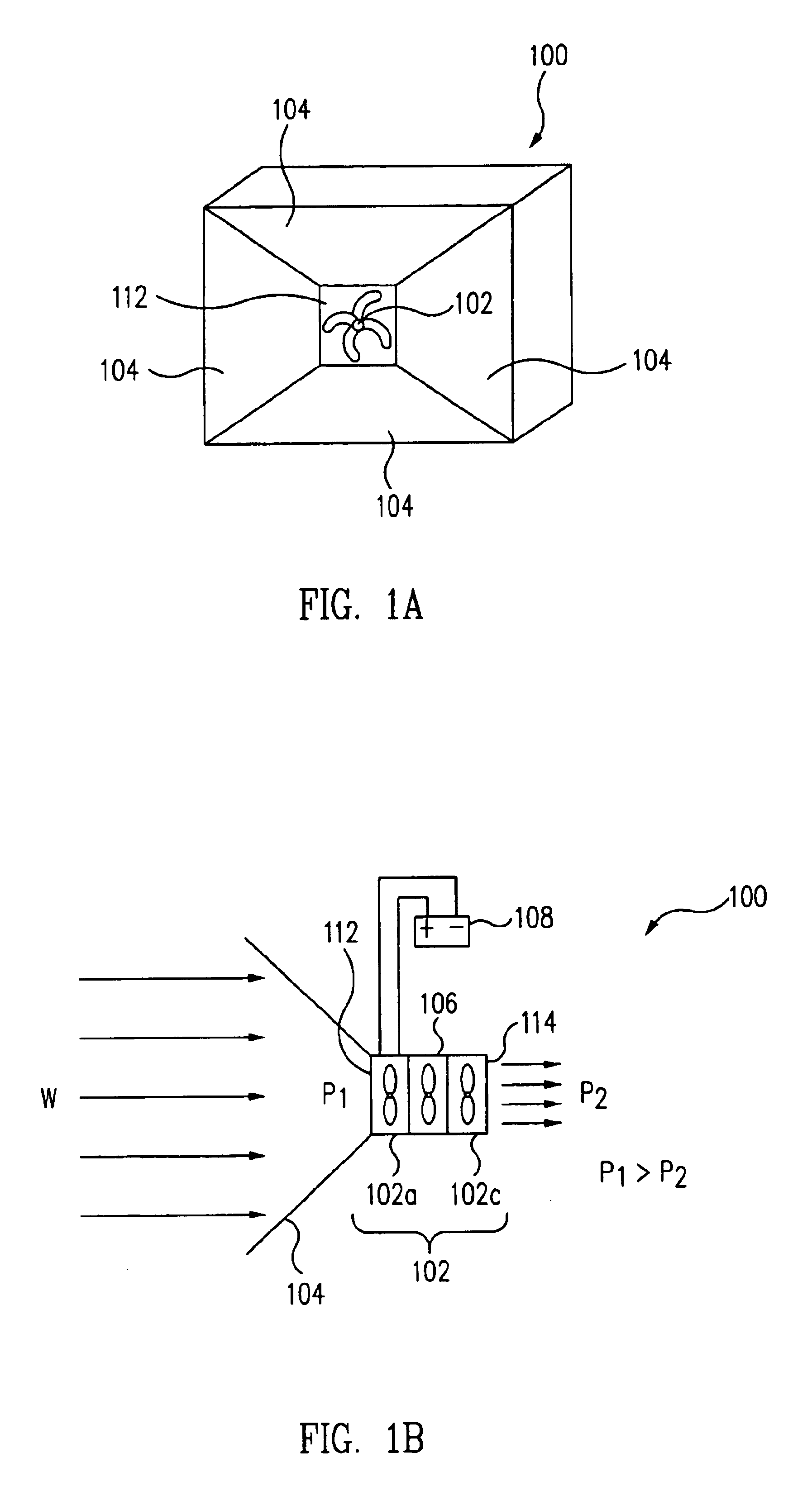
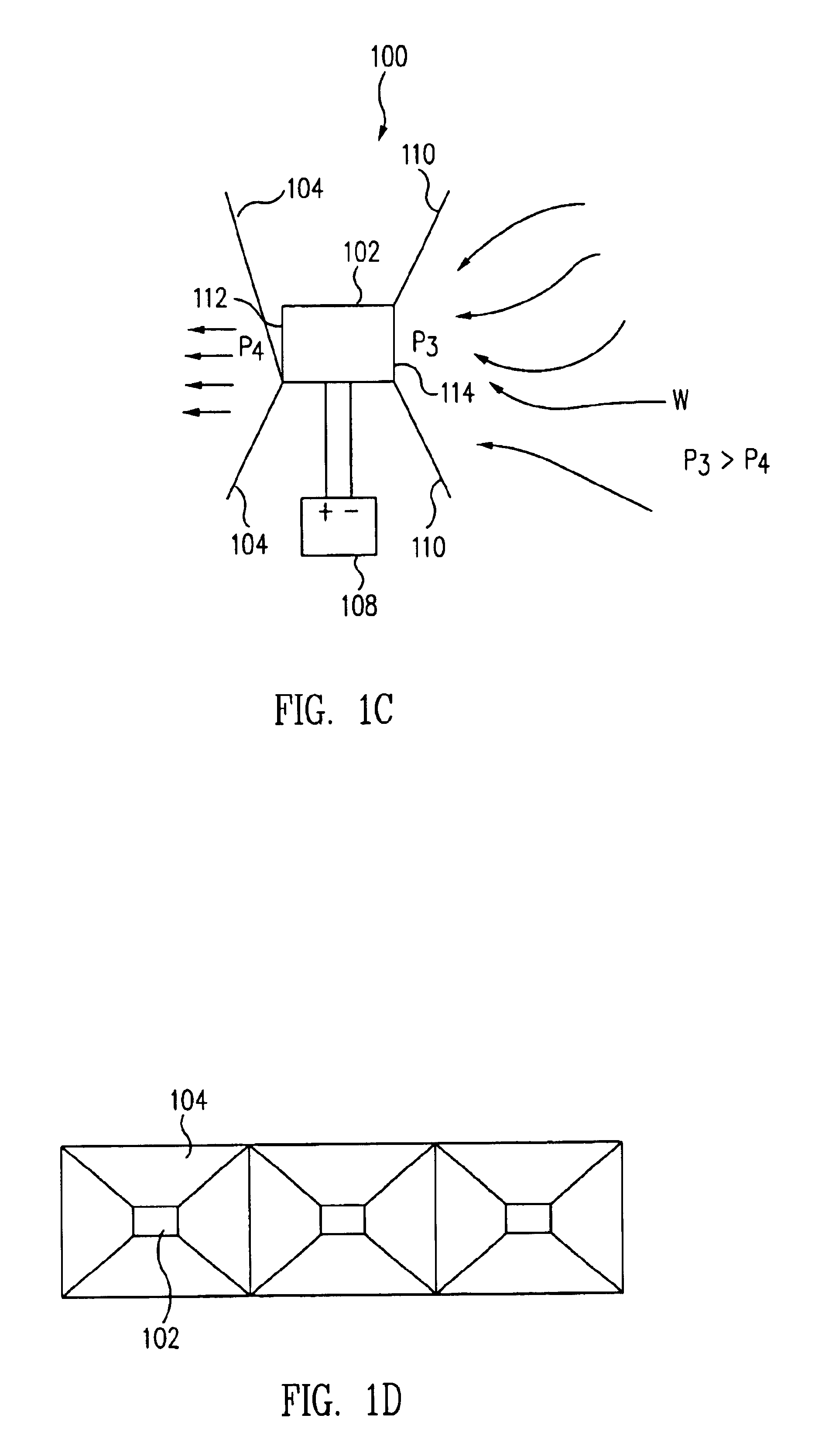
[0025]FIGS. 1A and 1B are simplified illustrations showing a wind power system 100 in accordance with an embodiment of the present invention. Wind power system 100 includes at least one generator fan 102, which functions as an electric drive generator, centered within wind capturing devices 104.

[0026]The principles of the invention are described in connection with a relatively small power system 100 using any relatively small to medium sized generator fan 102. Generator fan 102 can be a direct current (DC) generator, or a generator producing alternating current (AC), also known as an alternator. In one embodiment, generator fan 102 is a 1 to 100 V DC motor having a capacity to generate between about 0.5 to about 10,000 Watts of electrical power. Motors suitable for use in the present invention are widely known and are available, for example, from McMaster-Carr Supply Company.

[0027]Depending upon the specific use of power system 100, the current produced can be introduced directly in...


PUM


Abstract

A wind power system is provided including at least one generator fan having a front face and a rear face. The system also includes a first wind capturing device positioned proximate to the front face. The wind capturing device can be configured to capture wind to create a first pressure proximate to the front face that is greater than a second pressure proximate to the rear face. The pressure difference causes the captured wind to flow across the at least one generator fan from the front face to the rear face.

Description

BACKGROUND[0001]1. Field of Invention[0002]The present invention relates to a wind power system for generating electrical power.[0003]2. Related Art[0004]A typical wind power system includes two or three blades which rotate about an axis. The blades are provided perpendicular to the direction of wind flow, with suitable pitch so that the wind causes the blades to rotate about the axis. The rotational motion of the blades is used to drive a gear box that drives a generator, effectively converting the kinetic energy of the wind to electrical energy.[0005]Unfortunately, typical wind power systems require large propeller-like blades, which can be inefficient, to the point of being useless. Large blades are generally required to ensure that the blades can be rotated with sufficient speed to overcome the torque inherent in the generator. Inefficiencies are created due to considerable friction in the gear box, which adds to the torque. Thus, during instances of low or moderate wind flow, t...

Claims


Application Information

Patent Timeline
Patent Type & Authority Patents(United States)
IPC IPC(8): F03D1/00F03D1/02F03D7/02F03D7/00F03D1/04
CPCF03D1/04F05B2240/40Y02E10/72Y02E10/728F03D1/02F03D13/20F03D9/11F03D9/25
Inventor YOO, WOO SIK
Owner WAFERMASTERS
Why Eureka
Try Eureka