
Ceramic igniters with sealed electrical contact portion

a ceramic igniter and electrical contact technology, applied in the field of ceramic igniters, can solve the problems of preventing optimal functioning, affecting the operation of the cooking edifice, etc., and achieve the effect of enhancing the resistance to undeired moisture and/or oxygen penetration

Inactive Publication Date: 2005-08-23
COORSTEK INC
View PDF25 Cites 25 Cited by
  • Summary
  • Abstract
  • Description
  • Claims
  • Application Information

AI Technical Summary

Benefits of technology

[0009]We now provide new ceramic igniters that can exhibit significantly enhanced resistance to undesired moisture and / or oxygen penetration.
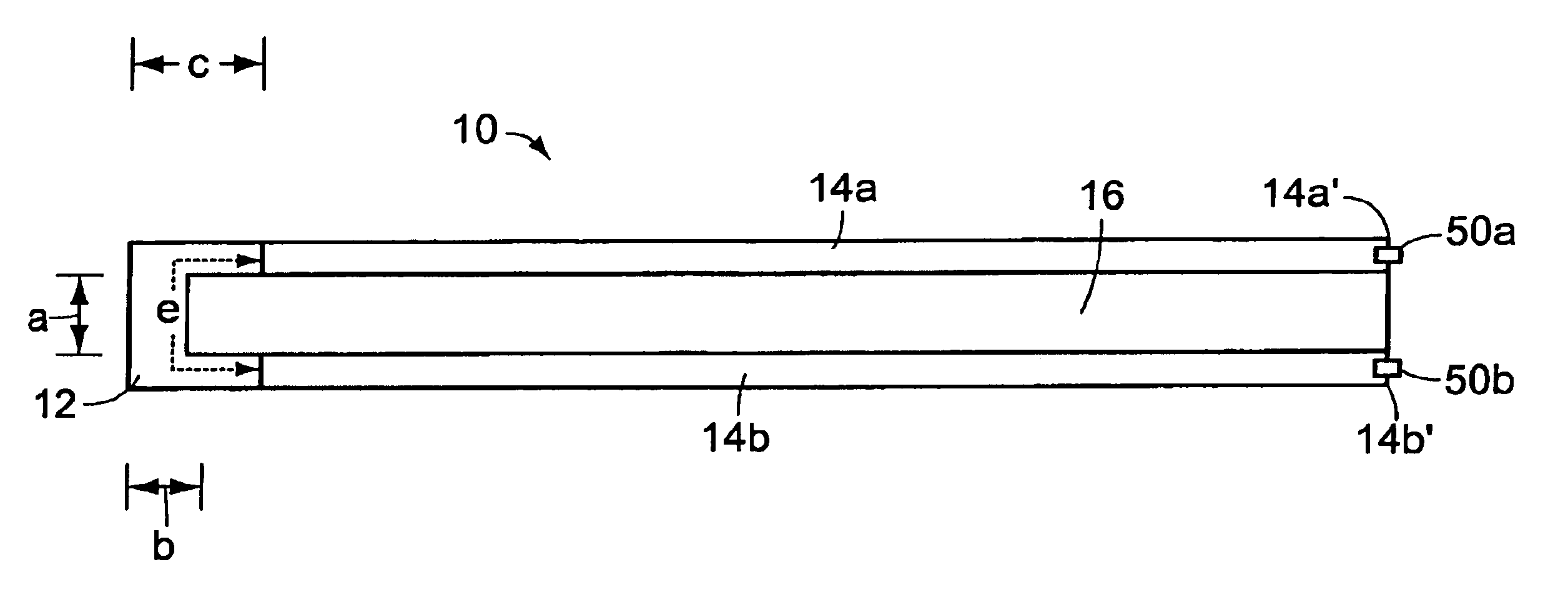
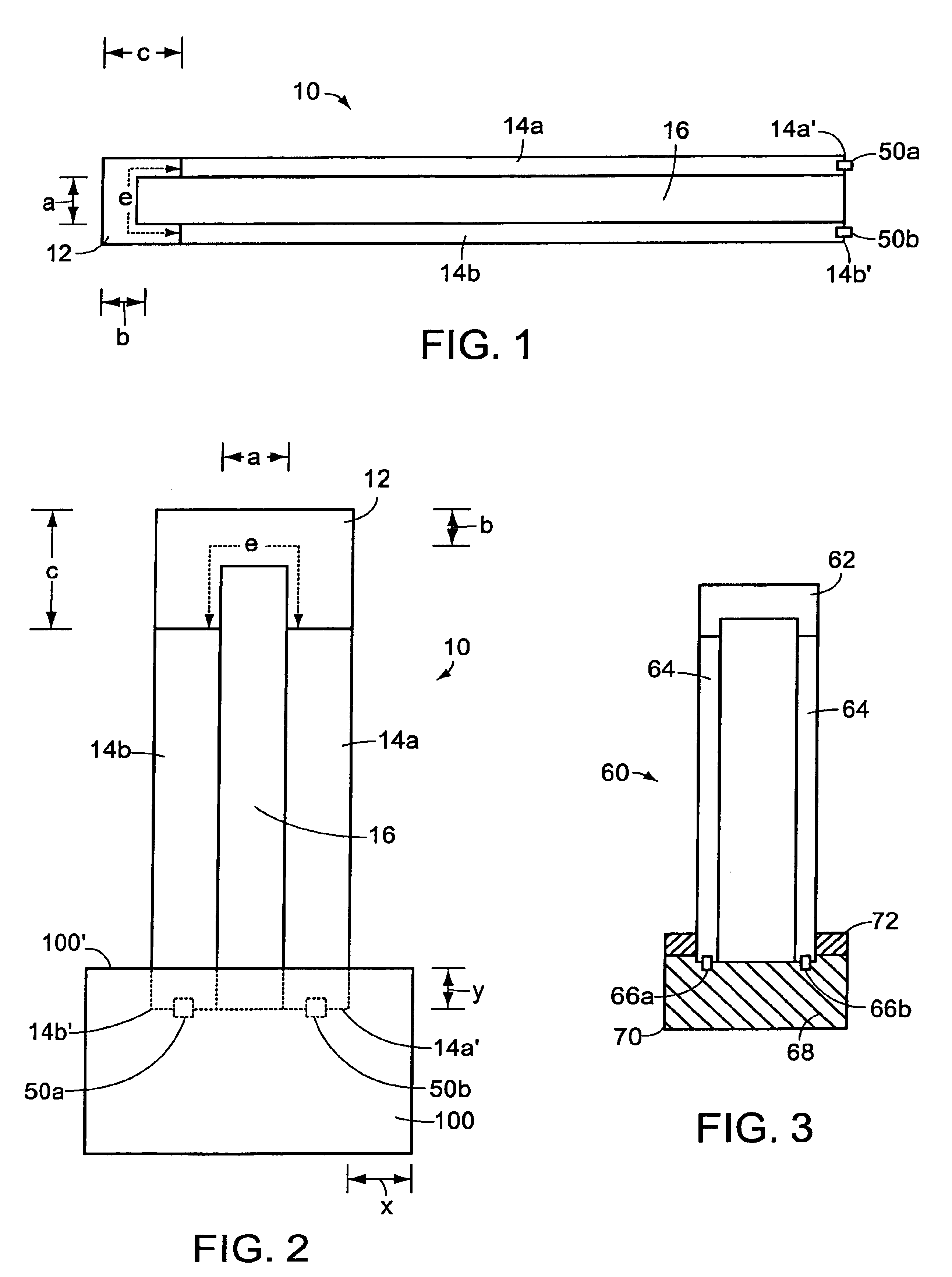
[0010]Preferred igniters of the invention are coated with or otherwise comprise at least in part a material that effectively inhibits entry of moisture and / or oxygen to an igniter's electrical contact portion. These coating compositions are generally referred to herein as a hermetic sealant material or composition. The hermetic sealant material suitably surrounds the electrical lead contact portion (typically distal to the igniter's hot zone region) to thereby insulate the electrical contact portion from undesired fluid / environmental contact.
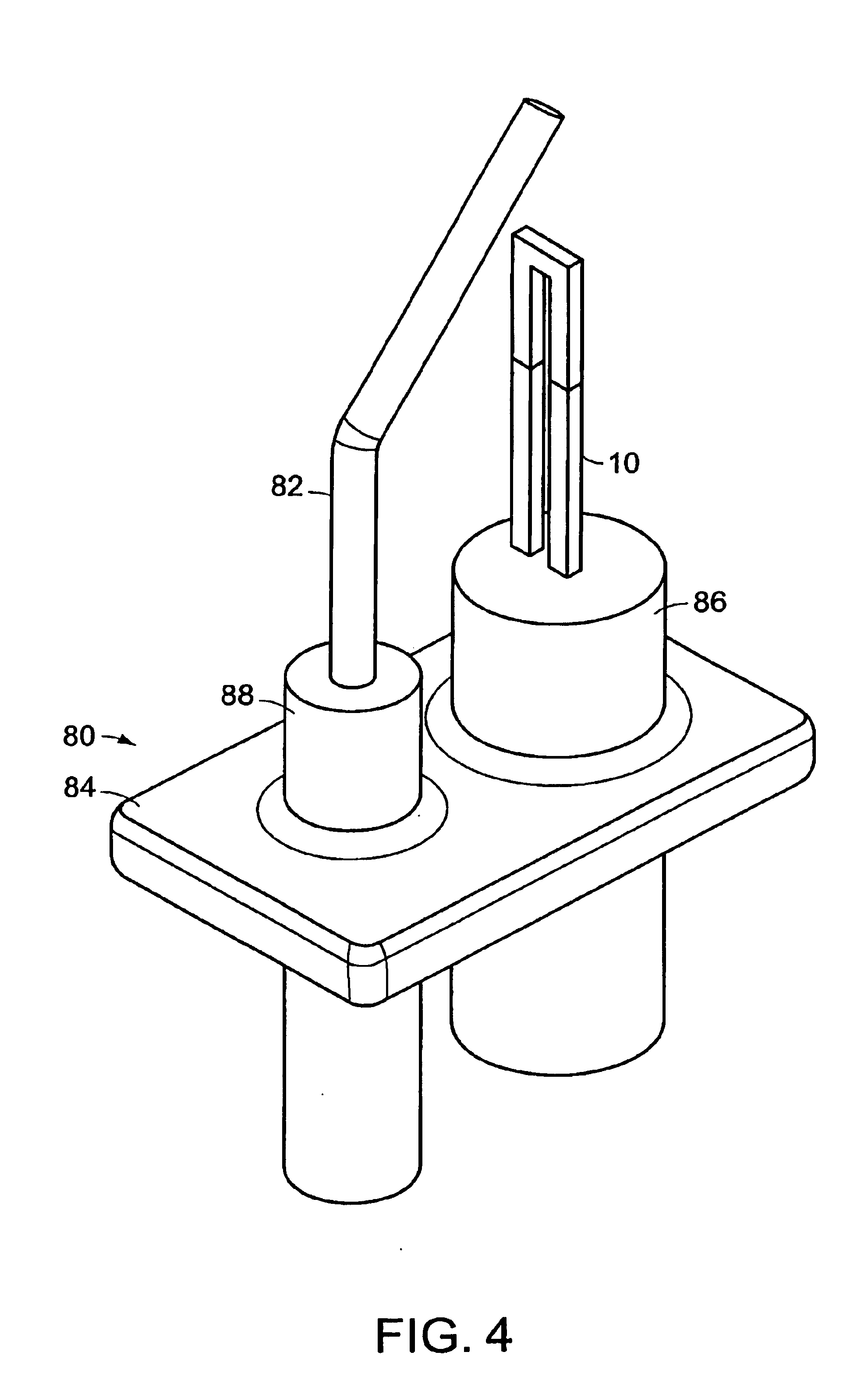
[0012]We also have found that use of a hermetic sealant material in accordance with the invention can enable manufacture of an igniter element with reduced cross-sectional profile. Igniters of such reduced dimensions can be useful in a variety of applications, including to retrofit gas burning apparatus designed for spark ignition.
[0013]Methods are also provided for manufacture of igniters of the invention, which include coating, particularly encapsulating, the electrical contact portion of an igniter with a sealant material in accordance with the invention. Suitably, the sealant material is applied to the igniter in an insert molding-type or batch-type process, i.e. where at least one igniter element, preferably a plurality of igniter elements, reside within a mold and a sealant composition is applied to the igniter electrical contact portion areas. An injection molding process also is preferred and can enable reduced manufacturing costs and times. Other approaches also are suitable, including transfer molding and compression molding.
[0019]In contrast, igniters of the invention do not require any such ceramic block, or other separate housing. Rather, the sealant composition itself can form an integral sealing member on the igniter, obviating the need for a separate housing unit. The absence of a separate housing unit also can provide an igniter system of smaller cross-sectional size and lower manufacturing cost.

Problems solved by technology

While ceramic igniter designs and performance have improved, problems still exist that can prevent optimal functioning.
One persistant problem is pentration of moisture or other fluids into the igniter electrical lead or contact portion, i.e. where electrical contacts mate with the igniter element, typically via a lead frame.
Cooking evironments are especially problematic.
Ceramic igniters used in gas stove settings frequently come into contact with spilled or splashed fluids (e.g. liquids, steam, etc.) emanating from pots or other apparatus on the stove.
Protective housing elements, particularly used in combination with a potting cement material (often an epoxy-based sealant), have been employed to avoid such fluid penetration, but such housings have not consistently provided satisfactory results.
If fluid penetrates the igniter's protective housing, and contacts the electric leads therewithin, the igniter can short circuit and fail.
Fluid penetration also can accelerate oxidation of the protected lead portion, which can result in premature igniter failure.

Method used


Image

  • Ceramic igniters with sealed electrical contact portion
  • Ceramic igniters with sealed electrical contact portion
  • Ceramic igniters with sealed electrical contact portion

Examples


example 1

[0089]An igniter of the invention is suitably prepared as follows.

[0090]Hot zone and cold zone compositions were prepared for a first igniter. The hot zone composition comprised 70.8 volume % (based on total hot zone composition) AlN, 20 volume % (based on total hot zone composition) SiC, and 9.2 volume % (based on total hot zone composition) MoSi2. The cold zone composition comprised 20 volume % (based on total cold zone composition) AlN, 20 volume % (based on total cold zone composition) SiC, and 60 volume % (based on total cold zone composition) MoSi2. The cold zone composition was loaded into a hot die press die and the hot zone composition loaded on top of the cold zone composition in the same die. The combination of compositions was densified together under heat and pressure to provide the igniter.

example 2

[0091]Electrical contacts were applied with a braze joint to two essentially identical igniters produced as described above in Example 1. Those two igniters are referred to as Igniter A and Igniter B below.

[0092]Igniter A was further processed in accordance with the invention. Specifically, Igniter A with electrical contacts thereon was placed in a mold and a ceramoplastic material available from Mykroy / Mycalex Ceramics added to the mold to encapsulate the contacts to provide an element of the design generally represented in FIG. 2.

[0093]For Igniter B, a cylindrical ceramic housing element was placed around the electrical contacts. An epoxy sealant was added to fill the housing element and encapsulate the contacts. The epoxy sealant was allowed to dry to cure.

[0094]The encapsulated electrical contact ends of each of Igniters A and B were placed in colored penetrating dye for about ten minutes. Upon cross-section analysis by visual (naked eye) inspection, no fluid was absorbed into t...


PUM

PropertyMeasurementUnit
temperatureaaaaaaaaaa
thicknessaaaaaaaaaa
thicknessaaaaaaaaaa

Abstract

Robust ceramic igniters are provided that include an improved sealing system which can significantly enhance operational life of the igniter. Preferred igniters comprise a conductive cold zone and hot zone with higher resisitivity. A hermetic sealant material covers one or more electrical connections on the of each cold zone, thus shielding the electrical connections from environmental exposure, and thereby avoiding igniter failure resulting from electrical shorts and / or undesired oxidation.

Description

[0001]The present application claims the benefit of U.S. provisional application No. 60 / 313,113, filed Aug. 18, 2001, which is incorporated herein by reference in its entirety.FIELD OF THE INVENTION[0002]The invention relates generally to ceramic igniters and, more particularly, to ceramic igniters that contain improved sealing for electrical contact portions of the device.BACKGROUND[0003]Ceramic igniters have found increased use in certain ignition applications such as gas fired furnaces, stoves and clothes dryers. See, generally, U.S. Pat. Nos. 3,875,477, 3,928,910, 3,974,106, 4,260,872, 4,634,837, 4,804,823, 4,912,305, 5,085,237, 5,191,508, 5,233,166, 5,378,956, 5,405,237, 5,543,180, 5,785,911, 5,786,565, 5,801,361, 5,820,789, 5,892,201, 6,028,292, and 6,078,028.[0004]While ceramic igniter designs and performance have improved, problems still exist that can prevent optimal functioning. One persistant problem is pentration of moisture or other fluids into the igniter electrical le...

Claims


Application Information

Patent Timeline
Patent Type & Authority Patents(United States)
IPC IPC(8): F23Q7/22F23Q7/00
CPCF23Q7/22F23Q13/00
Inventor HAMEL, SCOTT M.PIETRAS, JOHN D.
Owner COORSTEK INC
Learn More