Circuit arrangement

Inactive Publication Date: 2005-08-23
PHILIPS LUMILEDS LIGHTING CO LLC
View PDF5 Cites 33 Cited by
  • Summary
  • Abstract
  • Description
  • Claims
  • Application Information

AI Technical Summary

Benefits of technology

[0011]Good results have been obtained for embodiments of a circuit arrangement according to the invention, wherein circuitry I comprises a current source that generates a current that is proportional to Vin2. Such a current source can be realized in a simple and dependable way, in case the current source comprises a first voltage divider coupled to the input terminals, a first zener diode coupled to the first voltage divider and a switching element coupled to the first zener diode. In a preferred embodiment the current source comprises a second zener diode. The second zener diode allows circuitry I to render Ton proportional to 1/Vin2 for two different values of the input voltage (e.g. 12 V and 24 V). In addition to the current source, the control circuit preferably comprises a capacitor coupled to the current source, and a comparator equipped with a first comparator input terminal coupled to the capacitor, a second comparator input terminal coupled to an output terminal of a second voltage divider coupled to the output terminals of the circuit arrangement, and a comparator output terminal coupled to the control electrode of the switching element.
[0012]In case it is desirable to control the light output of the LED array operated by a circuit arrangement according to embodiments of the invention, the control circuit is preferably equipped with circuitry III for substantially square wave modulating the amplitude of the current through the output terminals. Circuitry III switches the current through the LEDs off during part of each period of the modulation and on duri

Problems solved by technology

Disadvantages, however, are that the control loop is expensive since it comprises many components and that the control loop is comparatively slow.
Furthermore, in case the actual value of the current is measured by measuring the voltage across an ohmic resistor that is placed in series with the output terminals, the control loop also causes a substantial power dissipation.
In most known circuit arrangements equipped with a current control loop comprising feedback, circuitry III cannot be comprised in the control cir

Method used


Image

  • Circuit arrangement
  • Circuit arrangement
  • Circuit arrangement

Examples


Embodiment Construction

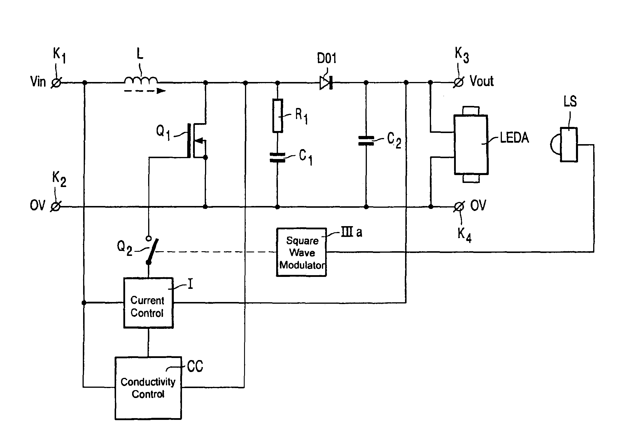
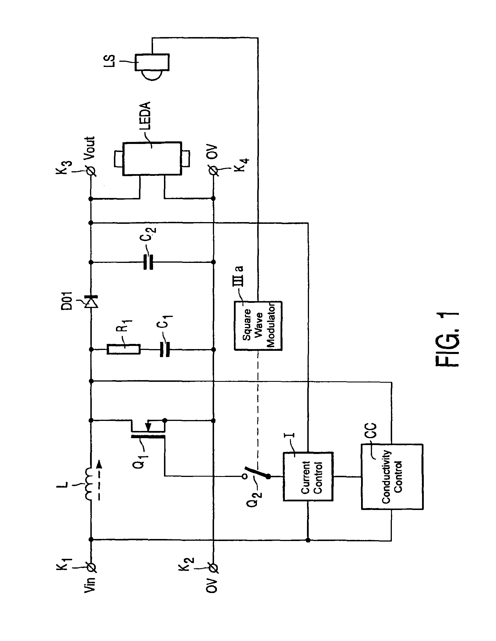
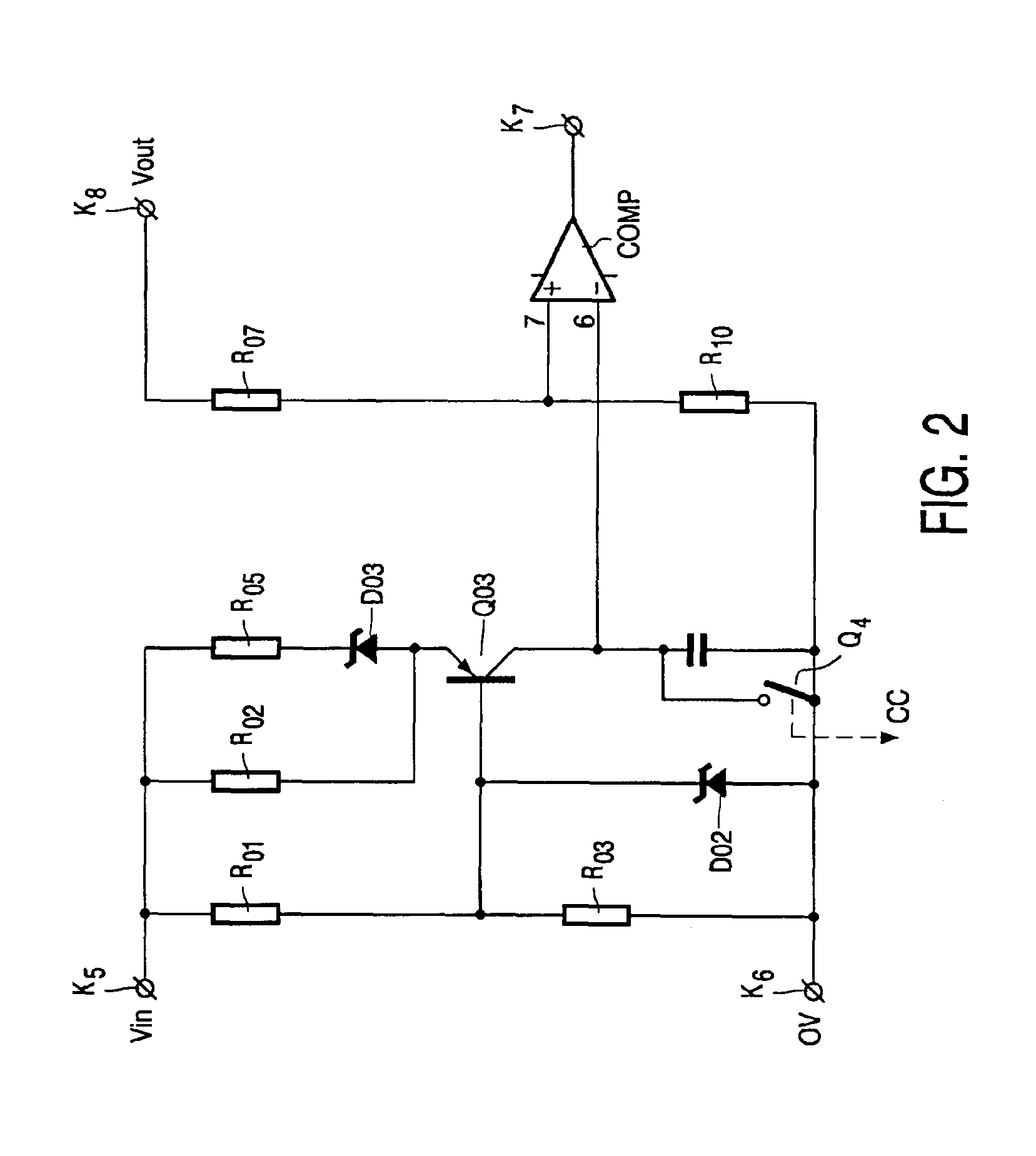
[0017]In FIG. 1, K1 and K2 are input terminals for connection to a voltage supply source. Input terminals K1 and K2 are connected by means of a series arrangement of inductive element L and switching element Q1. Switching element Q1 is shunted by a series arrangement of ohmic resistor R1 and capacitor C1 and by a series arrangement of diode D1 and capacitor C2. In this embodiment diode D1 forms a unidirectional element. Respective sides of capacitor C2 are connected with output terminal K3 and output terminal K4. An LED array LEDA is connected between output terminals K3 and K4. A control electrode of switching element Q1 is connected to an output terminal of circuit part I via a switching element Q2. Circuit part I forms circuitry I for controlling the current through output terminals K3 and K4 at a predetermined value. Respective input terminals of circuit part I are connected to input terminal K1, output terminal K3 and an output terminal of a circuit part CC. Circuit part CC is ...


PUM


Abstract

In an up-converter feed forward control of the output current is effected by rendering the conduction time of the switching element proportional to Vout/Vin2. This control is fast and avoids interference and loss of efficiency.

Description

BACKGROUND[0001]1. Field of Invention[0002]The invention relates to a circuit arrangement for supplying an LED array.[0003]2. Description of Related Art[0004]A circuit arrangement for supplying an LED array may include input terminals for connection to a voltage supply source, output terminals for connection to the LED array, and a DC—DC-converter coupled between the input terminals and the output terminals and equipped with an inductive element L, a unidirectional element, a switching element coupled to the inductive element and the unidirectional element, and a control circuit coupled to a control electrode of the switching element for generating a high frequency control signal for rendering the switching element conductive and non-conductive at a high frequency to thereby operate the DC—DC-converter in the critical discontinuous mode and equipped with means I for controlling the current through the output terminals at a predetermined value.[0005]Operation in the critical disconti...

Claims


Application Information

Patent Timeline
IPC IPC(8): G09G3/36H02M3/28G09G3/34H02M3/155G02F1/133H01L33/00G09G3/14H05B33/08G09G3/20H05B44/00
CPCH05B33/0815H05B33/0851H05B45/375H05B45/3725H05B45/38H05B45/385H05B45/12G02F1/133
Inventor BUCKS, MARCEL JOHANNES MARIACLAESSENS, JOHANNES MATHCUS THEODORUS LAMBERTUSDE KRIJGER, JOZEF PETRUS EMANUELNIJHOF, ENGBERT BERNARD GERARD
Owner PHILIPS LUMILEDS LIGHTING CO LLC
Why Eureka
Try Eureka