Wide bandwidth radar

a radar and wide-band technology, applied in the field of doppler radar, can solve problems such as detriment to radar and other band users

Inactive Publication Date: 2005-08-23
THE GENERAL ELECTRIC CO LTD +1
View PDF12 Cites 16 Cited by
  • Summary
  • Abstract
  • Description
  • Claims
  • Application Information

AI Technical Summary

Benefits of technology

[0008]Similar considerations apply to the receiving section of the system as to the transmission section. Means is therefore preferably included for separating a received signal into separate channels carrying components in different frequency bands. These separate channels lead to individual receivers designed to operate in the respective different frequency bands. The transmitters and receivers preferably share the same “common” channel and the same antenna. In such arrangement...

Problems solved by technology

These restrictions apply because known efficient means of amplification and control of radar frequency power tend to produce harmonic distortions and intermodulation products (especially if ...

Method used


Image

  • Wide bandwidth radar
  • Wide bandwidth radar
  • Wide bandwidth radar

Examples


Embodiment Construction

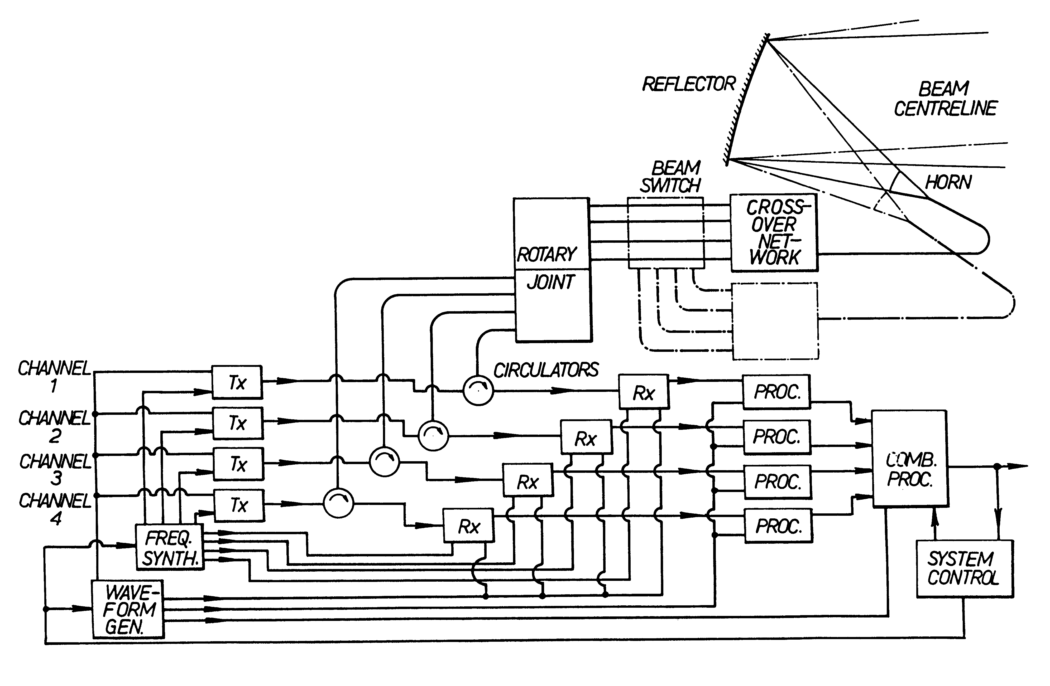
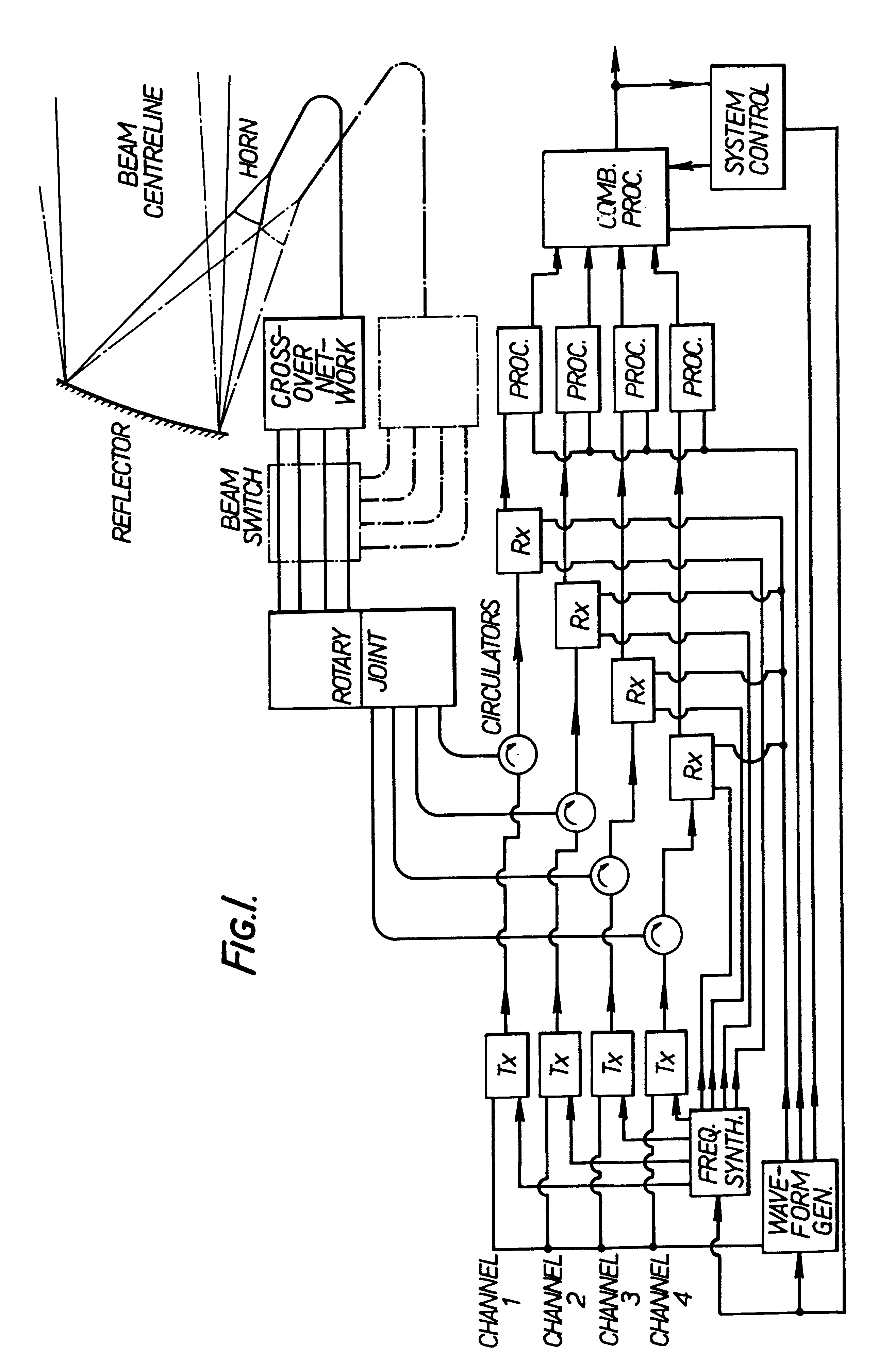
[0013]Referring firstly to FIG. 1 the illustrated radar system has a plurality of separate channels for the amplification of signals to be transmitted, and for the reception and Doppler processing, or alternative means of signal processing, of radar echoes. A single antenna 10 is provided for transmission and reception of all channels. The antenna is so constructed that the plurality of radar beams corresponding to the plurality of separate channels are superposed and co-directed so as to form in effect a single beam carrying the transmissions of, and collecting the echoes for, all channels. The antenna is also constructed so that portions of its structure which may be exposed simultaneously to signals from a plurality of channels include no components or materials having non-linear characteristics likely to cause harmonic or intermodulation distortions to such signals. An appropriate type of antenna is explained below.

[0014]Any plural number of channels may be provided, but arrange...


PUM


Abstract

A wave-form generator drives a number of microwave generating devices each operating at different frequency bands. The output of each microwave generator is connected to its own transmission channel of limited bandwidth which contains all the non-linear components necessary for transmission such as an amplifier, T/R switch, rotary joint and beam switch. These individual channels are finally combined onto a common wideband channel which contains only substantially linear components such as a single waveguide and the antenna itself. Because of the isolation between channels there is little or no opportunity for the generation of harmonics or intermodulation distortions which would otherwise occur in a transmitter capable of operating over a very wide bandwidth.

Description

BACKGROUND OF THE INVENTION[0001]This invention relates to a Doppler radar designed to operate over a wide bandwidth.[0002]For many years it has been considered desirable for military radars to be able to vary their nominal radar carrier frequency of transmission as widely and as agilely as posible in order to elude jamming and other hostile attentions. Such radars have hitherto generally been restricted to an agile range, or bandpass, of less than one octave, and are able generally to transmit on only one radar carrier frequency at once. These restrictions apply because known efficient means of amplification and control of radar frequency power tend to produce harmonic distortions and intermodulation products (especially if more than one radar carrier frequency is amplified simultaneously), detrimental to the radar and to other band users. Conventional radars employ waveguide components with sufficiently restricted bandpass characteristics so that the unwanted harmonic distortions ...

Claims


Application Information

Patent Timeline
IPC IPC(8): G01S13/00G01S13/02G01S7/03G01S7/28G01S7/282
CPCG01S7/032G01S13/0209G01S7/282
Inventor MOLYNEUX-BERRY, ROBERT BEWES
Owner THE GENERAL ELECTRIC CO LTD
Why Eureka
Try Eureka