Narrow reactive edge treatments and method for fabrication

a reactive edge treatment and narrow technology, applied in the direction of radiating element structural forms, resonance antennas, antenna couplings, etc., can solve the problems of limiting the range and reliability of radio devices using antennas, coupling reduces the efficiency of all antennas involved, and the energy may be coupled in an undesirable fashion

Inactive Publication Date: 2005-08-23
E TENNA CORP
View PDF4 Cites 47 Cited by
  • Summary
  • Abstract
  • Description
  • Claims
  • Application Information

AI Technical Summary

Benefits of technology

[0010]By way of introduction, the present invention provides an electromagnetic bandgap material that enables high isolation between antennas due to the attenuation of surface waves. The present invention further provides narrow artificial magnetic conductors (AMCs) whose physical width is less than 1 / 10 of a free space wavelength for the frequency of surface currents of interest. The present invention still further provides several embodiments of AMCs suitable for this purpose, along with several exemplary manufacturing techniques for the AMCs.
[0011]An AMC is an electrically thin, loss-less, reactive material that exhibits a high surface impedance and attenuates surface waves over a specific bandwidth. In this application, the AMCs are nominally λ / 50 in thickness. The ability of an AMC to suppress surface currents at frequencies within its bandgap and without degrading the efficiency of nearby antennas makes it attractive for applications where low mutual coupling between closely spaced antennas is required. One such application is in wireless devices that have 802.11 and Bluetooth radios.

Problems solved by technology

In many applications, two or more adjacent antennas may couple energy in an undesirable fashion.
The coupling reduces the efficiency of all antennas involved and may drastically limit the range and reliability of radio devices using the antennas.
The drawbacks with this solution include the mass of the MAGRAM material.
This will degrade antenna efficiency when placed within the antennas near field.
Also, as with the MAGRAM material, these materials are RF absorbers that will degrade antenna efficiency when used in the near field of an antenna.

Method used


Image

  • Narrow reactive edge treatments and method for fabrication
  • Narrow reactive edge treatments and method for fabrication
  • Narrow reactive edge treatments and method for fabrication

Examples


Embodiment Construction

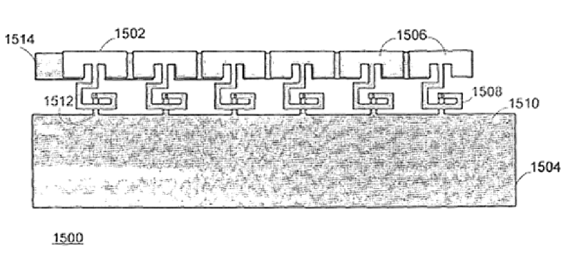
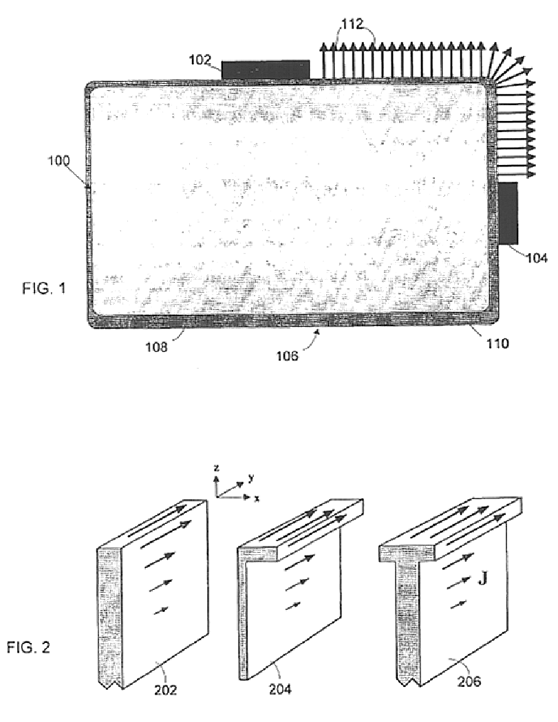
[0034]The present invention provides a reactive circuit intended to be integrated into, or attached to, the edge of a conductive ground plane or electrically thin conductive surface. Its purpose is to act as a choke for electric currents that can flow tangential to the edge of the conductive surface. The most common reason for such currents to exist is because they travel along with a radiated electromagnetic wave that is launched from an antenna located on or near the edge of the ground plane. By choking edge currents, one can increase the isolation between two antennas located on or near the edge of the ground plane without reducing the performance of the antennas.

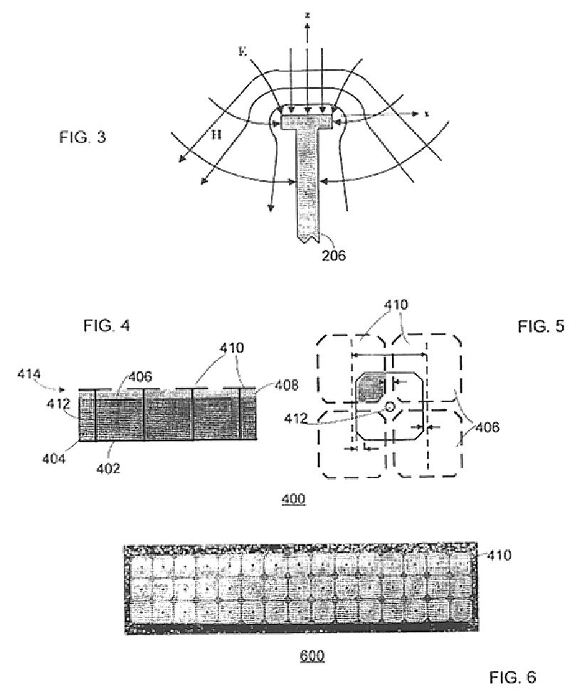
[0035]The present invention makes use of materials that may be characterized as artificial magnetic conductors. An artificial magnetic conductor (AMC) offers a band of high surface impedance to plane waves, and a surface wave bandgap over which bound, guided transverse electric (TE) and transverse magnetic (TM) modes can...


PUM


Abstract

An electromagnetic bandgap material is electrically attached to an edge, and enables high isolation between antennas due to the attenuation of surface waves. The disclosed embodiments further provide narrow reactive edge treatments in the form of artificial magnetic conductors (AMCs) whose physical width is less than 1 / 10 of a free space wavelength for the frequency of surface currents intended to be suppressed. These embodiments still further provide several AMCs suitable for this purpose, along with several exemplary manufacturing techniques for the AMCs.

Description

BACKGROUND[0001]The present invention relates generally to electromagnetic bandgap materials for isolating antennas. More particularly, the present invention relates to narrow reactive edge treatments and methods for manufacturing the same. One embodiment of the invention is a surface treatment that may be applied to laptop computers or other wireless devices.[0002]In many applications, two or more adjacent antennas may couple energy in an undesirable fashion. The coupling reduces the efficiency of all antennas involved and may drastically limit the range and reliability of radio devices using the antennas.[0003]One particular application which requires multiple antennas is a laptop computer with Bluetooth and wireless local area network (WLAN) capabilities. Bluetooth is a wireless data communication standard operating at approximately 2.4 GHz with a range of approximately 10 meters. WLAN data standards include a group of standards propounded by the Institute of Electrical and Elect...

Claims


Application Information

Patent Timeline
Patent Type & Authority Patents(United States)
IPC IPC(8): H01Q1/00H01Q1/52H01Q15/00
CPCH01Q1/521H01Q15/008
Inventor MENDOLIA, GREG S.ROGERS, SHAWNMCKINZIE, III, WILLIAM E.
Owner E TENNA CORP
Why Eureka
Try Eureka