
Multichannel access point with collocated isolated antennas

a technology of isolated antennas and access points, which is applied in the direction of individual energised antenna arrays, independent non-interacting antenna combinations, and radiating element structural forms, etc., and can solve the problems of scaling limitations, inability to achieve throughput increases, and limited fdm

Inactive Publication Date: 2005-08-23
CISCO TECH INC
View PDF16 Cites 85 Cited by
  • Summary
  • Abstract
  • Description
  • Claims
  • Application Information

AI Technical Summary

Problems solved by technology

However, FDM is typically limited by the channel availability of the selected wireless network standard.
However, if channel coverages are overlapped, the resulting mutual interference imposes a scaling limitation on the network, and no throughput increase can be obtained.
Also, interference is high between transmit and receive channels within collocated or nearby radio components due to antenna-to-antenna coupling, multipath interference, and electronics coupling.
However, TDM is limited by standards and only available if supported therein.
While the current standards may limit throughput efficiency, compatibility requirements with the standard precludes the implementation of a TDM system.
However, the current AP standards do not permit incorporation of such spread spectrum modulation and multiplexing.
However, performance suffers in an indoor environment containing metal grids and other multipath and depolarization propagation phenomena.
Therefore, polarization diversity is not viable at the present time without employing real-time adaptive combinational techniques.
However, such systems rely on large, expensive high-rejection multiplexing filters to separate transmit channels so as to not interfere with receivers on adjacent beams.
This is not a suitable approach for WLAN applications due to both size and cost.
None of the above-noted solutions can satisfy the goal of raising throughput while conforming to presently accepted wireless network standards, though FDM suffers from the least number of drawbacks.
However, with such an approach it would be difficult using known techniques to avoid interference of the adjacent or alternate channels used for transmission and reception of signals.

Method used


Image

  • Multichannel access point with collocated isolated antennas
  • Multichannel access point with collocated isolated antennas
  • Multichannel access point with collocated isolated antennas

Examples


Embodiment Construction

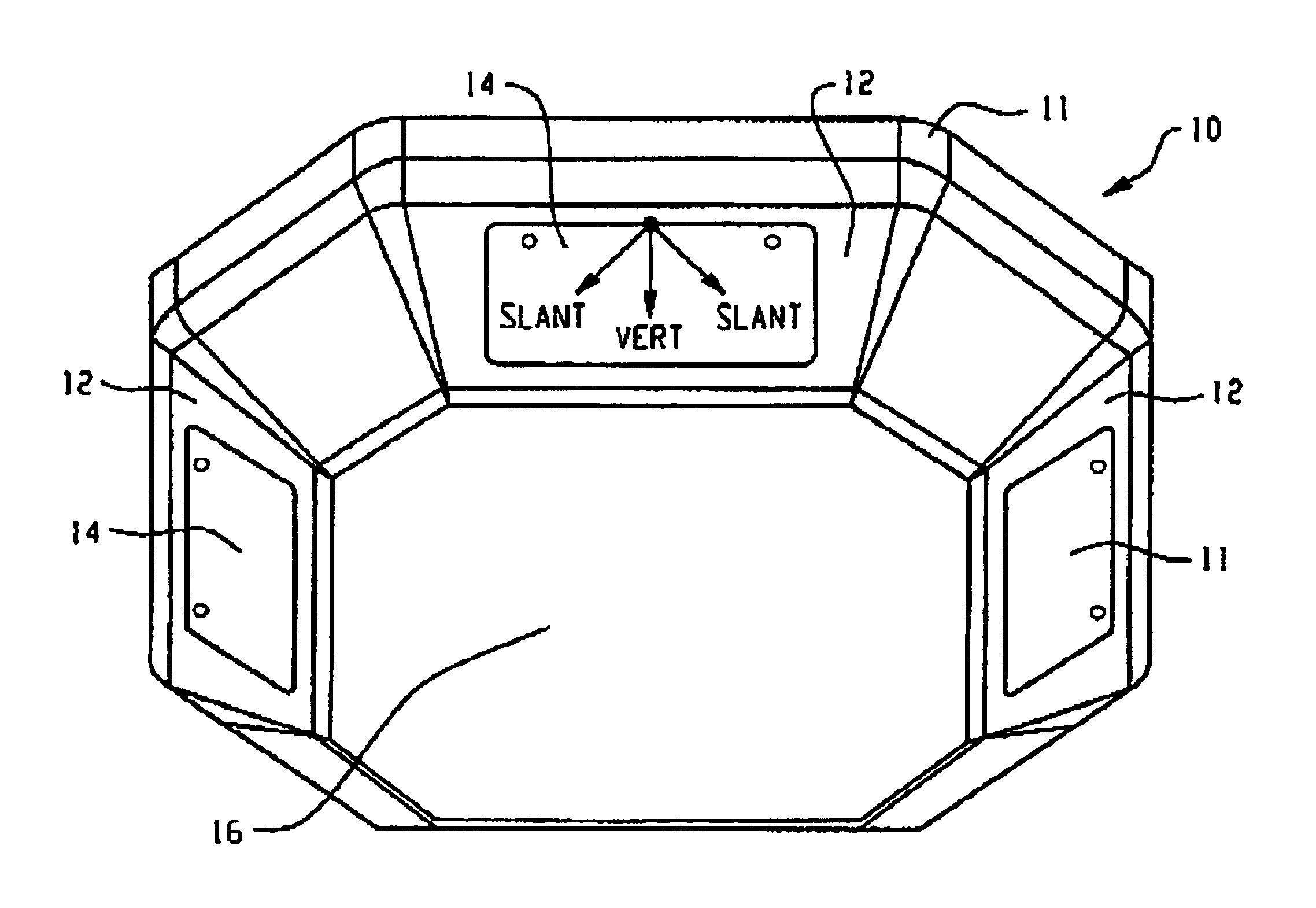
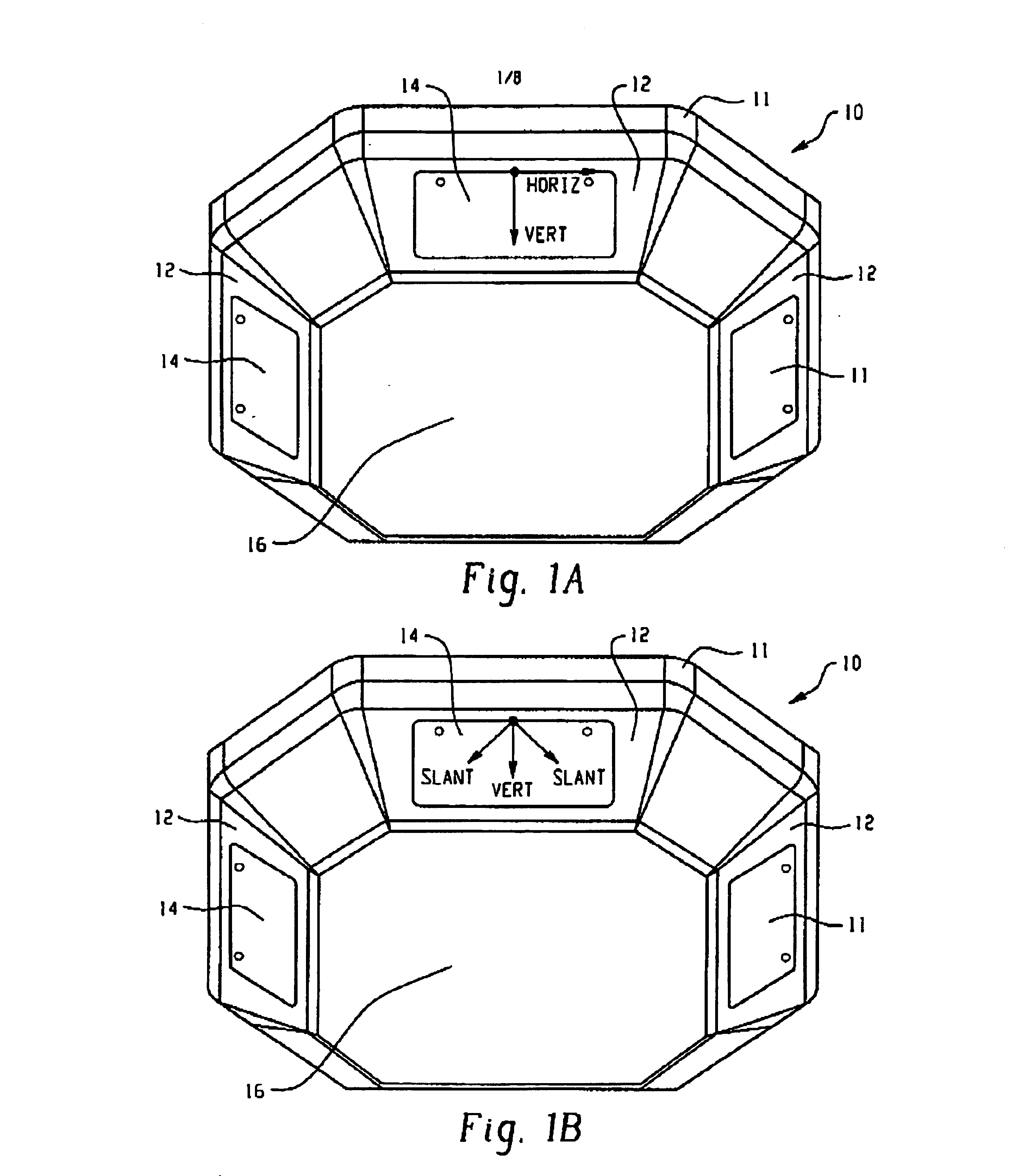
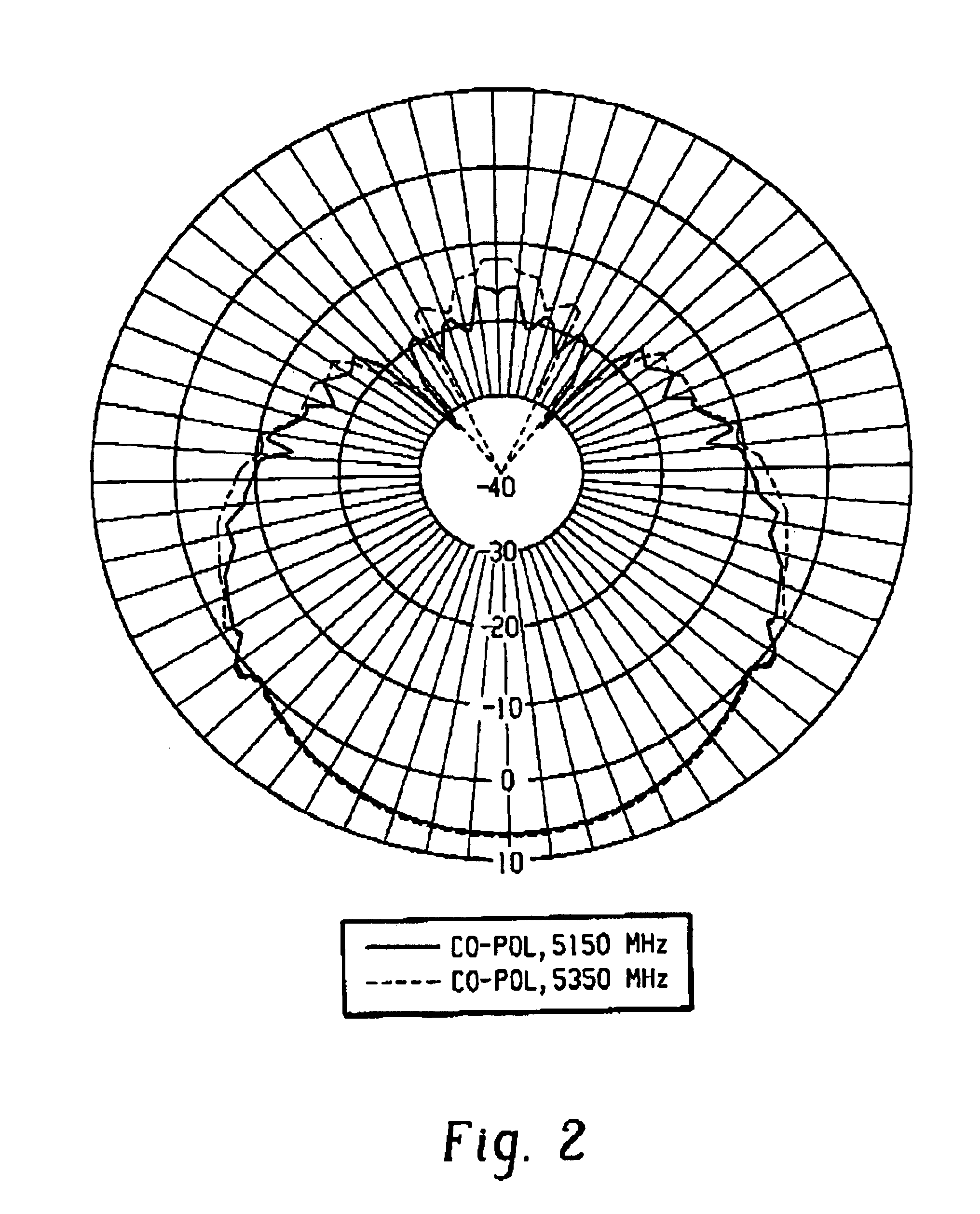
[0023]A multichannel access point is disclosed herein that reduces channel-to-channel interference by providing a number of collocated, isolated antennas, as will be set forth in detail below. In the preferred embodiment, the present multichannel AP divides an omnidirectional coverage area into discrete sectors so that a particular one of a plurality of wireless antennas is used to transmit and receive wireless signals into a specific sector of the omnidirectional space. Throughput over the omnidirectional coverage area is thereby raised by a factor equal to the number of sectors.

[0024]In one aspect of the present invention, a plurality of patch antennas is employed. In the preferred embodiment, a linearly polarized patch antenna having a parasitic element can be used, such as is disclosed in U.S. Ser. No. 10 / 146,609, the disclosure of which is hereby incorporated by reference. Such a patch antenna has a desirable front-to-back ratio and low depolarization. It has been found that mo...


PUM


Abstract

A wireless telecommunications device is disclosed including a plurality of wireless antennas, each respectively for transmitting and / or receiving wireless signals into a predetermined sector of an omnidirectional space. A mounting structure is included for retaining the respective plurality of wireless antennas, wherein the mounting structure is configured so as to isolate the respective wireless signals.

Description

BACKGROUND OF THE INVENTION[0001]The present application discloses embodiments directed to wireless access points for use with a wireless local area network (WLAN). In a typical wireless access point (AP), a single or dual band radio component is operated with one or more omnidirectional or directional antennas having moderate gain. The supportable throughput of an AP is typically determined by the antenna coverage pattern combined with the signal rate and modulation type provided by the radio component. With an increase of wireless traffic in a particular coverage area, it is desirable to service more users on a dense client area. It would thus be desirable to increase throughput of an AP. Several approaches have previously been used, including frequency, time, code, and polarization division multiplexing.[0002]With Frequency Division Multiplexing (FDM), a number of signals are combined into a single channel, where each signal is transmitted over a distinct frequency sub-band withi...

Claims


Application Information

Patent Timeline
IPC IPC(8): H01Q1/00H01Q1/52H01Q21/28H01Q21/20H01Q25/00H01Q21/00
CPCH01Q25/00H01Q1/007H01Q1/521H01Q21/20H01Q21/28
Inventor THEOBOLD, DAVID M.
Owner CISCO TECH INC
Learn More