Optical scanning system

Inactive Publication Date: 2005-08-23
BROTHER KOGYO KK
View PDF5 Cites 18 Cited by
  • Summary
  • Abstract
  • Description
  • Claims
  • Application Information

AI Technical Summary

Benefits of technology

[0011]When the optical scanning system as described above is used, in particular, as a multi-beam scanning optical system in an image forming apparatus, a variance of magnification in the sub-scanning direction influences the quality of image as variance of a scanning line pitch. However, the variance of a value determined by multiplying the distance from the exit surface of the second lens containing the maximum power in the sub-scanning direction to the surface to be scanned by the incident angle is substantially equal to the variance of magnification in the sub-scanning direction. By satisfying the above inequality, the variance of the scanning line pitch can be reduced to within ±10%, a

Problems solved by technology

Further, this structure can greatly reduce power in the main scanning direction, required for a

Method used


Image

  • Optical scanning system
  • Optical scanning system
  • Optical scanning system

Examples


Example

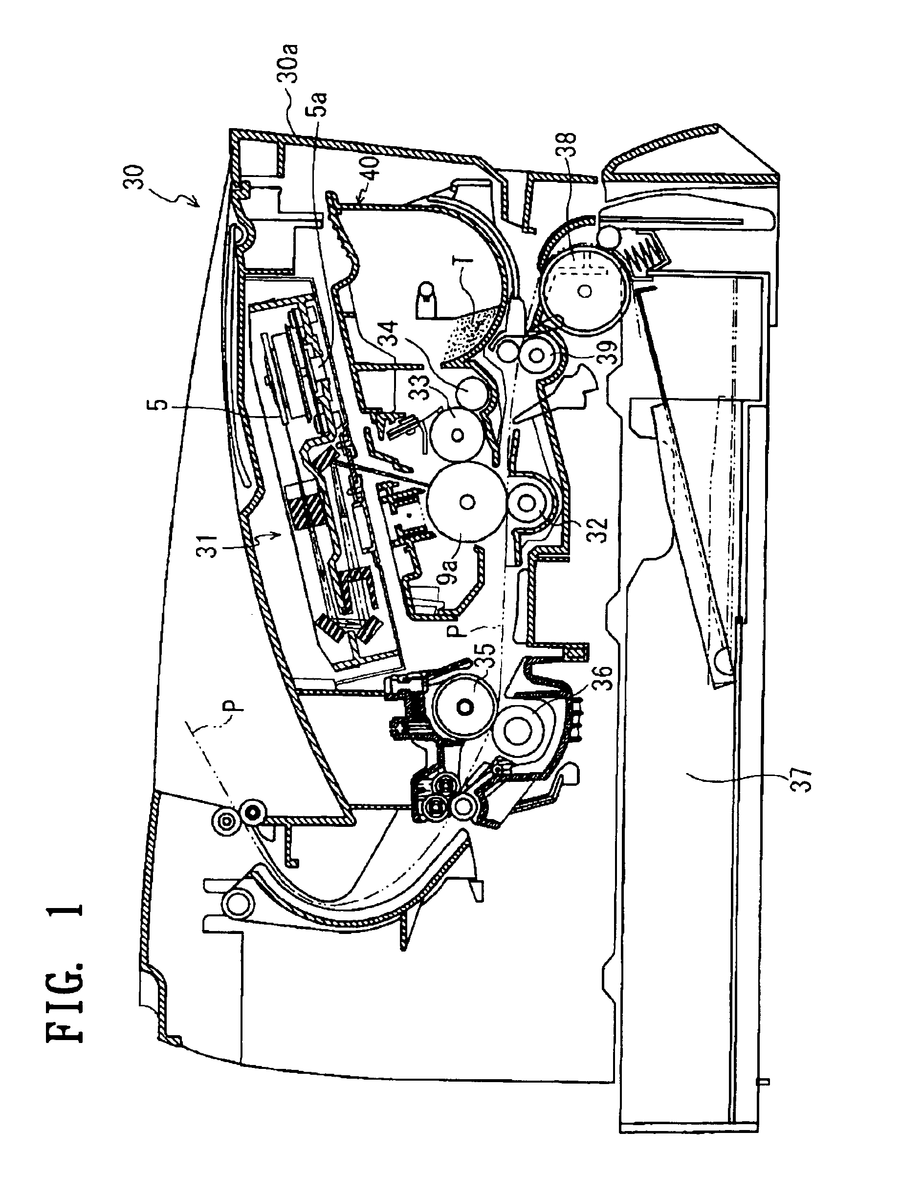
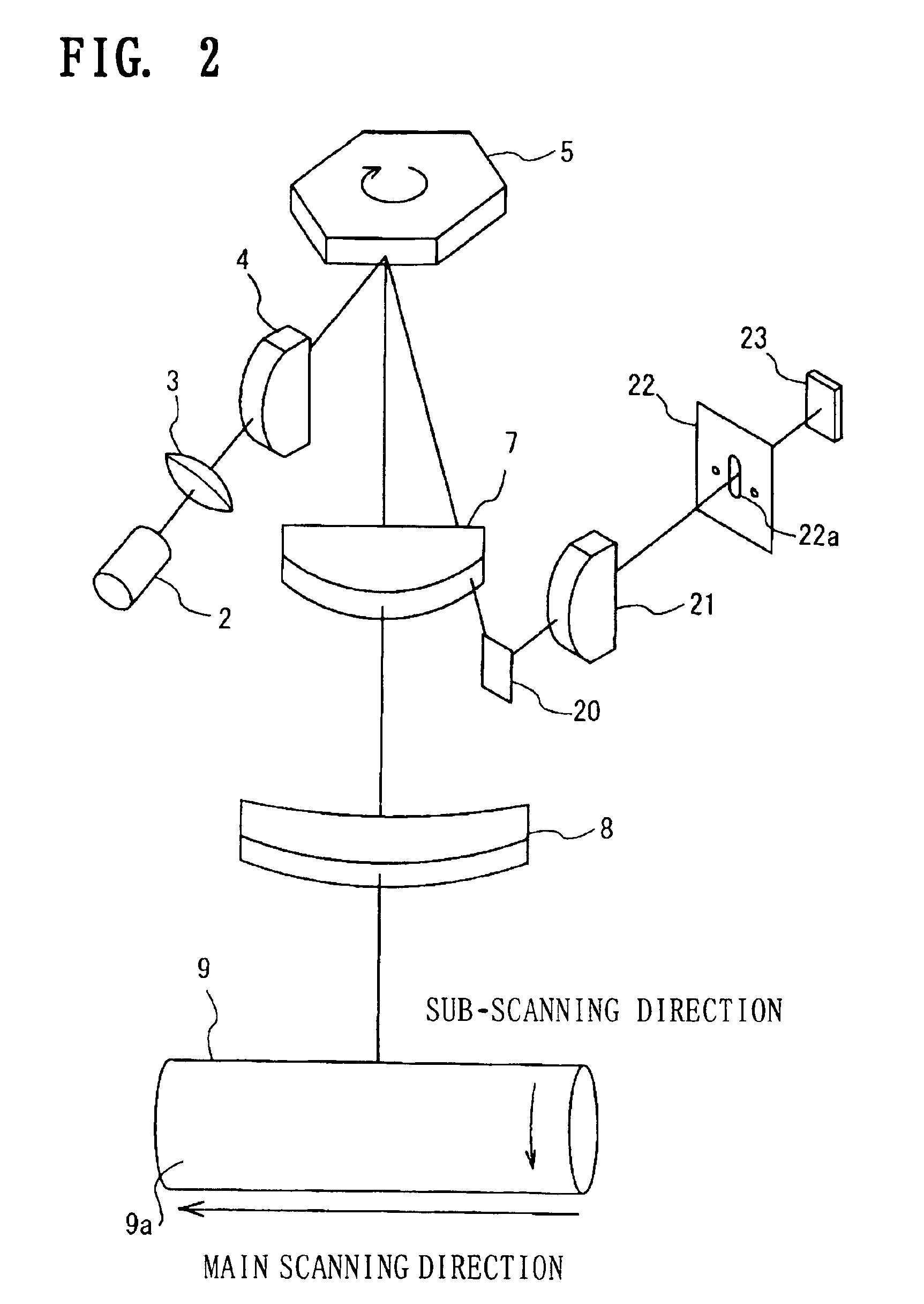
[0023]A preferred embodiment of the invention will be described in detail with reference to the accompanying drawings. FIG. 1 is a cross sectional view of a laser printer 30 incorporating a laser scanner unit 31 according to an embodiment of an optical scanning system of the invention. FIG. 2 is a schematic view of an optical system inside the laser scanner unit 31.

[0024]A structure of the laser printer 30 will be described with reference to FIG. 1. As shown in FIG. 1, the laser printer 30 includes the laser scanner unit 31 and a photosensitive unit 40 in substantially a cuboid casing 30a. A sheet cartridge 37 is detachably provided at a lower portion of the laser printer 30. Sheets of paper P are stacked in the sheet cartridge 37, each of the sheets is conveyed to a lower part of the photosensitive unit 40 by a sheet feed roller 38 and a conveyor roller 39. Toner T is contained in the photosensitive unit 40, and supplied to a developing roller 33 by a toner supply roller 34. From t...


PUM


Abstract

A multi-beam scanning optical system includes a light source, a collimating lens, a cylindrical lens, a polygon mirror, and an fθ lens system. The fθ lens system is made up of a first fθ lens whose entrance surface and exit surface have rotational symmetries, and a second fθ lens whose entrance surface has a rotational symmetry and exit surface has a rotational asymmetry. In the first fθ lens, the entrance surface is a spherical surface, and the exit surface thereof is an aspherical surface. The entrance surface of the second fθ lens is an aspherical surface, and the exit surface thereof is a toroidal surface with aspheric contour in a cross section taken along the main scanning direction. The second fθ lens is physically shaped so as to satisfy the inequity 0.9<(Le×cos θ)/Lc<1.1.

Description

BACKGROUND OF THE INVENTION[0001]1. Field of Invention[0002]The invention relates to an optical scanning system for use with an image forming apparatus.[0003]2. Description of Related Art[0004]Conventionally, in an optical scanning system used in an image forming apparatus, such as a laser printer, image recording is performed by emitting a collimated beam of light from a light source, focusing the beam on a reflective surface of a deflector through a cylindrical lens placed in front of the deflector in a sub-scanning direction, and focusing the deflected beam on a surface to be scanned using an fθ optical system that scans with constant velocity thereon.[0005]In a conventional fθ optical system, focal points in the main scanning direction and the sub-scanning direction are likely to vary back and forth in accordance with a scanning position. Therefore, in designing an fθ lens, attention has been directed toward reducing curvature of field to within an acceptable limit. When a laser...

Claims


Application Information

Patent Timeline
IPC IPC(8): G02B26/12G02B13/00B41J2/44G02B13/08G02B13/18G02B26/10H04N1/036H04N1/113
CPCG02B13/0005G02B26/125
Inventor KATO, RYOTA
Owner BROTHER KOGYO KK
Why Eureka
Try Eureka