Ranging apparatus, ranging method, and opto-electric conversion circuit

a technology of ranging apparatus and conversion circuit, which is applied in the direction of distance measurement, instruments, surveying and navigation, etc., can solve the problems of difficult to accurately measure distances, affecting flexibility, functionality, etc., and achieves accurate distance measurement, reduce the effect of variance, and reduce the peak effect of varian

Inactive Publication Date: 2005-08-23
NIKON CORP
View PDF21 Cites 17 Cited by
  • Summary
  • Abstract
  • Description
  • Claims
  • Application Information

AI Technical Summary

Benefits of technology

[0053]Thus, with the fifth and sixth ranging apparatus, the frequency distribution table is produced using a count that has undergone moving averaging, rather than using the count directly as it comes from the counter. Accordingly, in cases where the distance is measured by looking at the object of measurement through window glass or tree branches, even when there is a frequency with a large peak in the frequency distribution table due to reflected light from the window glass, etc., or even when there is a frequency with a large peak due to noise light, the peak can be lowered by performing moving averaging in which an average frequency is taken of a plurality of frequencies including of this peak and of those before and after this peak, allowing the distance to the object of measurement to be measured accurately.
[0054]Moreover, even if there is variance in the position at which the frequency increases in the frequency distribution table due to the shaking of the user's hands when the ranging apparatus is held in the hands during measurement, atmospheric fluctuations in the measurement environment, and other such effects, the distance can still be measured accurately by using moving averaging to reduce the effect of this variance. Furthermore, when measuring the distance to an object of measurement having longitudinal spread (that is, with depth), as is the case when measuring the distance to a building whose walls are viewed obliquely, the count increases over a wide range of distances, but if this frequency is subjected to moving averaging, the middle position in this broad distance range can be ascertained, so that accurate distance measurement will still be possible.
[0055]Specifically, by performing moving averaging, the frequencies with large peaks that occur in the frequency distribution table are smoothed out, the middle part of a frequency that increases over a broad range can be emphasized, the effect of high noise frequencies can be eliminated, the middle part of a broad range can be ascertained, and accurate distance measurement will be possible even in the above-described situations.

Problems solved by technology

However, when an object of measurement is thus irradiated with pulsed laser light and the light reflected back from the object of measurement is then received, what is received is not only the reflected laser light, but also natural light and so forth, which becomes noise light.
This noise light is difficult to distinguish from the light reflected back from the object of measurement, so the problem is that it is difficult to measure distances accurately.
Unfortunately, however, the following problems are encountered with this ranging method.
The first problem is as follows: Specifically, when the object of measurement is large and all of the laser light emitted from the ranging apparatus irradiates the object of measurement, it seems sufficient to calculate the distance corresponding to the point showing a high count in the frequency distribution table, but when the object of measurement is relatively small and the laser light also irradiates the area surrounding the object of measurement, so that reflected light from surrounding objects also comes back, or when there are a plurality of objects of measurement at varying distances within the laser light irradiation field of the ranging apparatus, so that reflected light comes back from each of the objects of measurement, there are a plurality of points showing high counts in the frequency distribution table.
In cases such as these, a plurality of distances are calculated, but the issues of how to handle the plurality of distances and how to display them greatly affect the flexibility, functionality, and so forth of the ranging apparatus.
In a case such as this, there is the danger that the count corresponding to the distance of the window glass will increase in the frequency distribution table, so that the distance corresponding to the position of the window glass will be mistakenly determined as the distance to the object of measurement.
Similarly, if tree branches or the like are in front of the object, the reflected light from the tree branches is received, and these branches may end up being mistakenly judged to be the object of measurement.
The third problem is as follows: Namely, when a distance is measured by looking at the object of measurement through window glass, or when a distance is measured by looking at the object of measurement through tree branches, the reflected light from the window glass, tree branches, or the like, located in front of the object of measurement is also constantly received.
Consequently, there is the danger that the frequency corresponding to the distance of these obstacles will be high in the frequency distribution table, so that the distance thereof will be determined as the distance to the object of measurement, the result being that the measured distance to the object of measurement is inaccurate.
Furthermore, the position at which the frequency in the frequency distribution table increases can be affected by the shaking of the user's hands when the ranging apparatus is held in the hands during measurement, atmospheric fluctuations in the measurement environment, and other such effects, which is a problem in that the measured distance is inconsistent, or frequencies with an extremely large peak appearing to be noise may occur in the frequency distribution table, and the direct use of these frequencies results in incorrect distance measurement.
Also, when the distance to an object of measurement that spreads out longitudinally is measured, such as when the distance to a building is measured by looking obliquely at the walls of the building, it is difficult to determine the distance if the frequency increases over a wide range of distances.
Consequently, it is extremely difficult to determine the level of frequency for the distance in the frequency distribution table to be taken as the position of the object of measurement.
In this case, if the preset determination threshold is too high, there is a concern that no frequency over this threshold will be found, and the distance to the object of measurement cannot be specified, but on the other hand, if the determination threshold is too low, many frequencies over this threshold may be found, making it impossible to specify which of these is the distance to the object of measurement.
Furthermore, in a laser ranging apparatus such as this, the intensity of the reflected light weakens as the distance to the object of measurement increases, so high sensitivity is required to detect faint light, and an extremely short time must also be detected accurately.
However, because of their high sensitivity, avalanche photodiodes also have the drawback of low stability.
However, temperature affects the breakdown voltage, so if the reverse bias voltage is close to the breakdown voltage, a change in the breakdown voltage will greatly alter the current multiplication factor.
When this happens, if the avalanche photodiodes are used with a laser ranging apparatus to detect reflected light from an object of measurement, the output from the detector changes independently of the amount of reflected light, producing an error in the measurement timing for received reflected light, and in extreme cases measurement may not even be possible.
In the former case, the cost of the apparatus increased by the cost of the device used to keep the temperature constant, and in the latter case, because there was a limit to the amount of light that could be detected, the measurable distance became shorter when the avalanche photodiodes were used with a laser ranging apparatus.

Method used


Image

  • Ranging apparatus, ranging method, and opto-electric conversion circuit
  • Ranging apparatus, ranging method, and opto-electric conversion circuit
  • Ranging apparatus, ranging method, and opto-electric conversion circuit

Examples


Embodiment Construction

[0093]Embodiments considered to be the best mode for carrying out the present invention are described below through reference to drawings, but these descriptions should not be construed to limit the scope of the present invention.

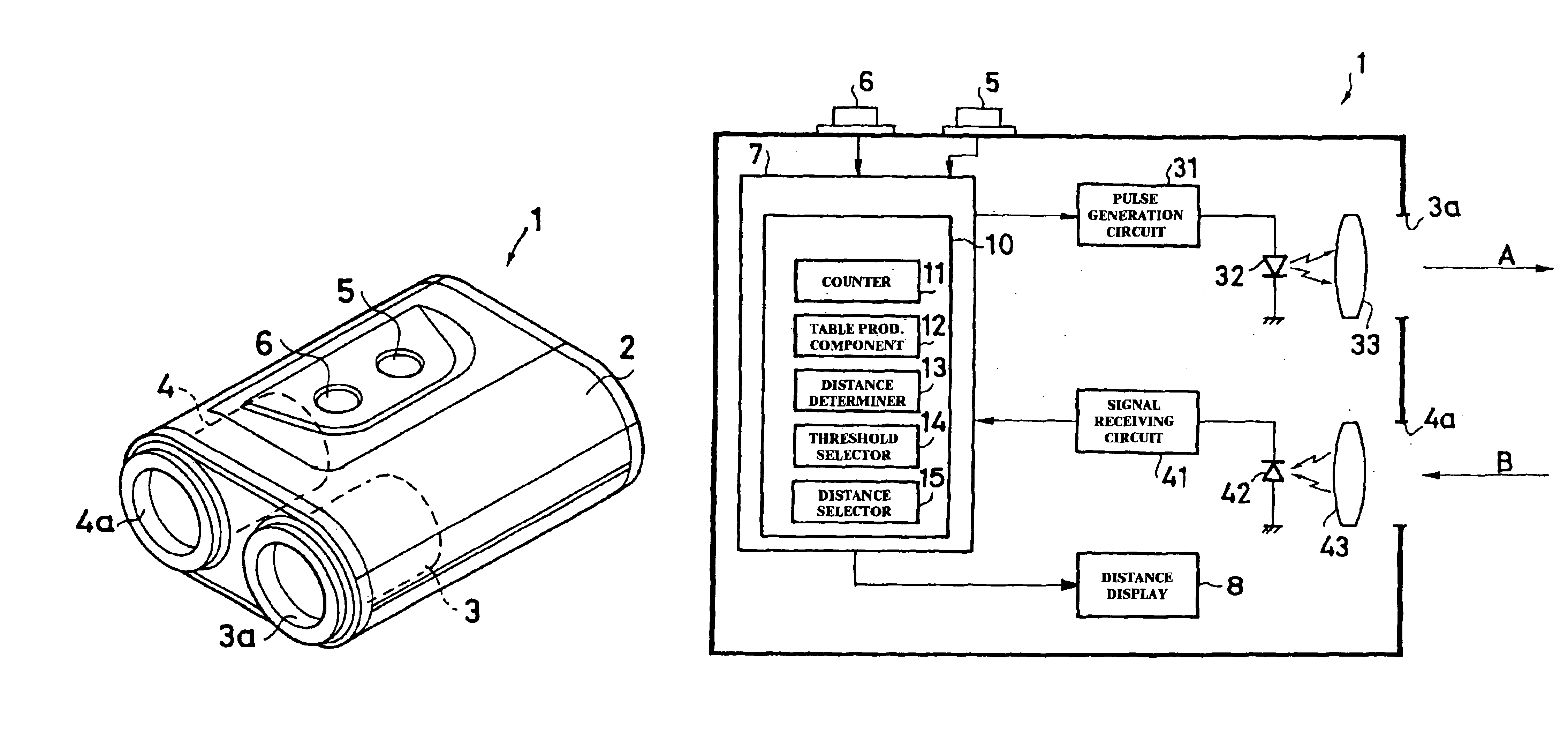
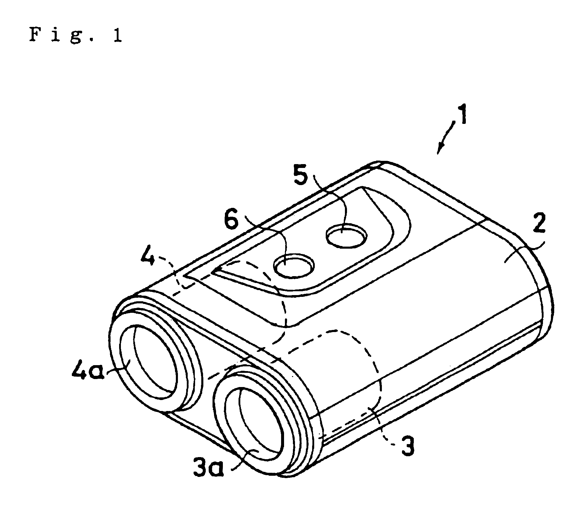
[0094]FIG. 1 shows a ranging apparatus 1 that is a first embodiment of the present invention. This ranging apparatus 1 consists of a laser light emitter 3 and a reflected light receiver 4 housed in a case 2. A laser light emission window 3a through which pulsed laser light (measurement light) from the laser light emitter 3 is emitted, and a reflected light reception window 4a through which reflected light is received, are provided to the case 2. A first control button 5 for switching the power on and off and commencing ranging, and a second control button 6 for display selection, are provided on the upper surface of the case 2. A finder window 2a (see FIG. 3) is provided on the back surface of the case 2, and the user (who uses this ranging apparatus 1 to p...


PUM


Abstract

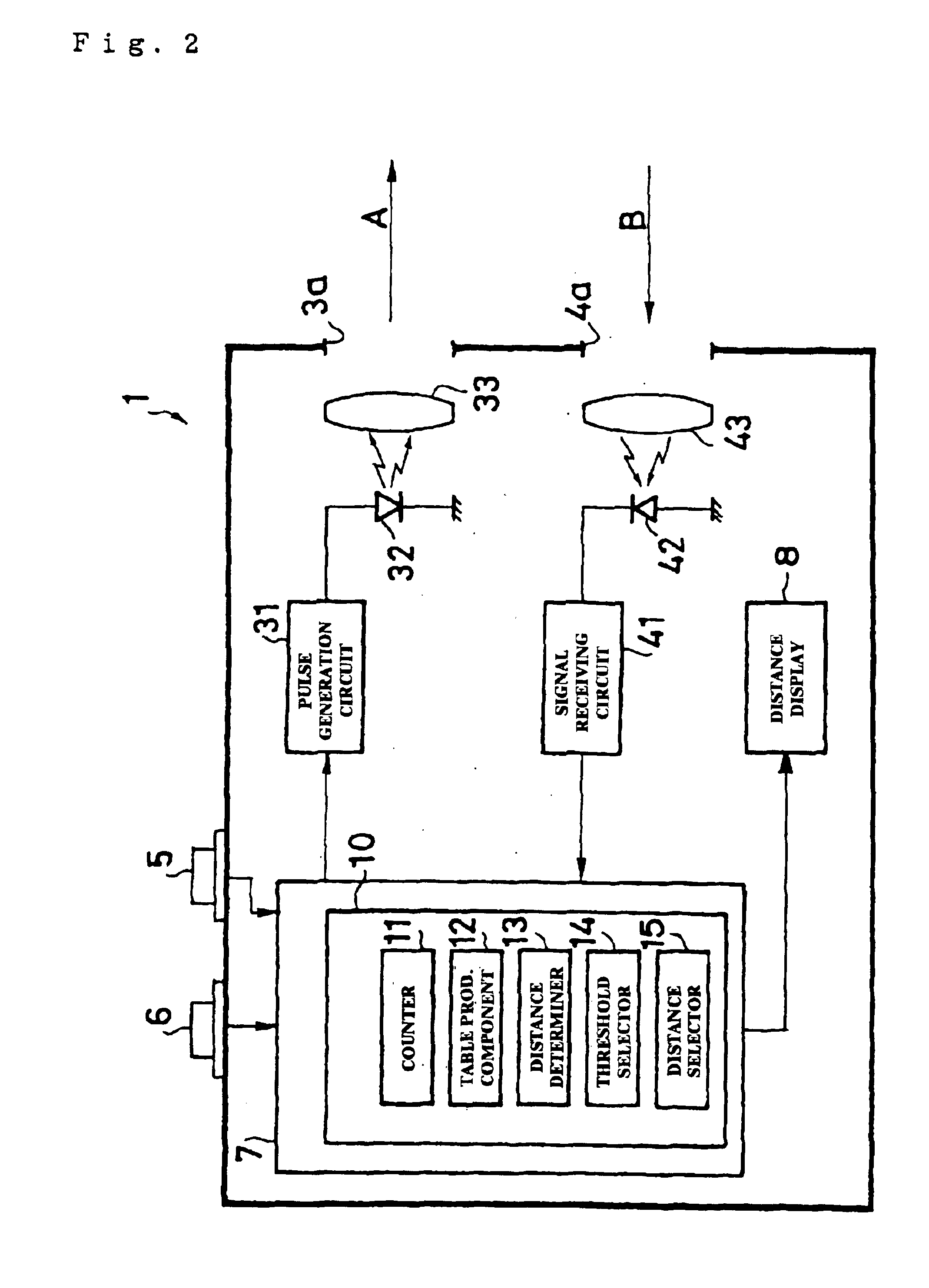
A ranging apparatus 1 comprises a laser light emitter 3 for emitting pulsed laser light, a reflected light receiver 4 for receiving reflected light, a distance computer 10 for finding the distance from the elapsed time until the reflected light is received, and a distance display 8 for displaying this distance. The distance computer 10 has a counter 11 for counting the frequency when the reflected light satisfies a specific condition, a table production component 12 for producing a frequency distribution table corresponding to distance by adding up the counts, a distance determiner 13 for determining as the distance to the object of measurement the point when the frequencies in the frequency distribution table exceed a threshold, and a distance selector15 for selecting a specific distance when a plurality of distances are determined, and displaying this distance on the distance display 8. As a result, when a plurality of distances are calculated, these distances can be appropriately displayed, improving the flexibility and functionality.

Description

[0001]The present application is a continuation of PCT International Application No. PCT / JP02 / 04122 filed Apr. 25, 2002, which is hereby incorporated by reference.TECHNICAL FIELD[0002]This invention relates to a ranging apparatus and ranging method with which laser light or the like is used to measure the distance to an object of measurement by a non-contact method, and to an opto-electric conversion circuit that can be used to advantage in such a ranging apparatus.BACKGROUND ART[0003]In conventionally known ranging apparatus and methods of this kind, pulsed measurement light (such as laser light) is emitted toward the object of measurement, the time it takes for the light to be reflected back from the object of measurement and received is measured, and the distance to the object of measurement is calculated from this elapsed time and the propagation speed of the laser light. However, when an object of measurement is thus irradiated with pulsed laser light and the light reflected ba...

Claims


Application Information

Patent Timeline
Patent Type & Authority Patents(United States)
IPC IPC(8): G01S17/10G01S17/00G01S7/48G01S7/487G01S17/18
CPCG01S17/10G01S17/107G01S7/4873G01S17/18
Inventor INABA, NAOTONAGASAWA, MASAYA
Owner NIKON CORP
Why Eureka
Try Eureka