Contactless electrical energy transmission system having a primary side current feedback control and soft-switched secondary side rectifier

a technology of contactless electrical energy transmission and feedback control, which is applied in the direction of electrical variable regulation, process and machine control, instruments, etc., can solve the problems of low efficiency and unregulated delivery of power to load, low parasitic ringing and loss, and power transmission via inductive coupling of ceet transformers. achieve the effect of constant energy transfer

Active Publication Date: 2005-08-23
DELTA ELECTRONICS INC
View PDF6 Cites 210 Cited by
  • Summary
  • Abstract
  • Description
  • Claims
  • Application Information

AI Technical Summary

Benefits of technology

[0009]Briefly, according to the present invention, a contactless electrical energy transmission system couples a power source to a load. The system includes a transformer having a primary winding that is coupled to the power source through a primary resonant circuit of an inverter and a secondary winding that is coupled to the load through a secondary resonant circuit of a rectifier. The primary and secondary resonant circuits are inductively coupled to each other. A primary control circuit is responsive to a current change through the primary resonant circuit to control the switching frequency of a controllable switching device for maintaining a substantially constant energy transfer between the primary winding and secondary winding in response to either one or both of a power source voltage change and a load change.
[0010]According to another aspect, a secondary control circuit generates one or more pulse width modulated control signals for

Problems solved by technology

However, power transmission via the inductive coupling of the CEET transformer has certain drawbacks in terms of low efficiency and unregulated delivery of power to the load.
The CEET primary and secondary windings can store high amounts of leakage inductance energy that can cause high parasitic ringing and losses.
Moreover, in CEET systems, it is very difficult to regulate power transmission mainly because there is no physical connection betwee

Method used


Image

  • Contactless electrical energy transmission system having a primary side current feedback control and soft-switched secondary side rectifier
  • Contactless electrical energy transmission system having a primary side current feedback control and soft-switched secondary side rectifier
  • Contactless electrical energy transmission system having a primary side current feedback control and soft-switched secondary side rectifier

Examples


Embodiment Construction

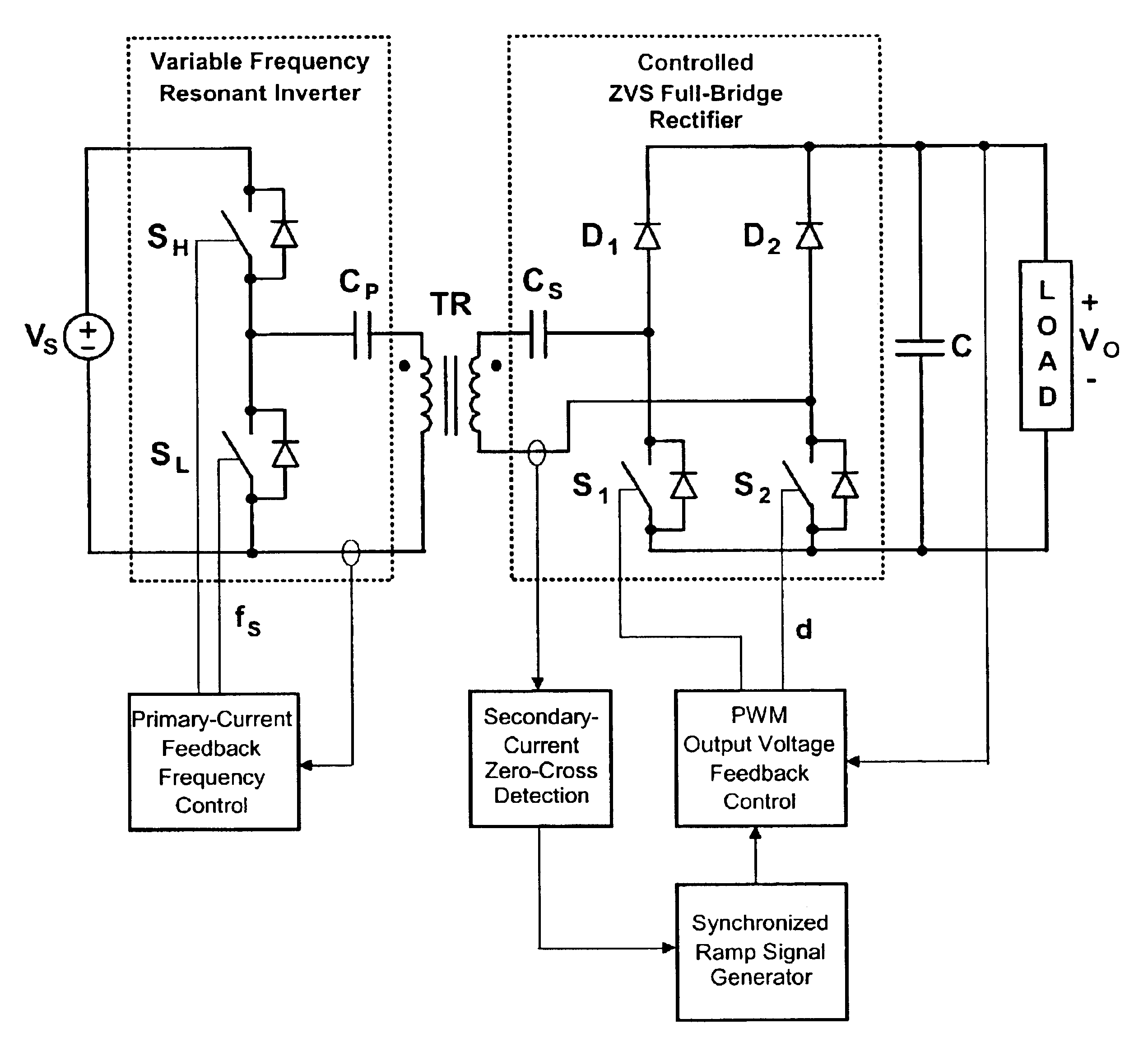
[0021]FIG. 3 shows an exemplary block diagram of the CEET system in accordance with the present invention. The system of FIG. 3 includes a variable frequency resonant inverter at a primary side and a controlled rectifier at a secondary side that includes a load. The primary side and secondary side are inductively coupled through the primary and secondary windings of a transformer. As shown, the inverter couples a power source having a power voltage VS to the primary winding through a primary resonant circuit comprising inductive and capacitive elements in the primary side. As described later in detail, a primary-current feed back frequency control block controls a primary switching frequency for regulating the power transfer between the primary and secondary sides. On the secondary side, the rectifier, which is a controlled zero-voltage switching (ZVS) rectifier, couples the secondary winding to a load through a secondary resonant circuit comprising inductive and capacitive elements...


PUM


Abstract

A contactless electrical energy transmission system includes a transformer having a primary winding that is coupled to a power source through a primary resonant circuit and a secondary winding that is coupled to a load through a secondary resonant circuit. The primary and secondary resonant circuits are inductively coupled to each other. A primary control circuit detects current changes through the primary resonant circuit to control the switching frequency of a controllable switching device for maintaining a substantially constant energy transfer between the primary winding and secondary winding in response to at least one of a power source voltage change and a load change. As a result, excessive circulating energy of the CEET system is minimized providing a tight regulation of the output voltage over the entire load and input voltage ranges without any feedback connection between the primary side and the secondary side.

Description

FIELD OF THE INVENTION[0001]Generally, the present invention relates to the field of contactless electrical energy transmission (CEET) systems, more particularly, to CEET systems that provide highly regulated power to a load.BACKGROUND OF THE INVENTION[0002]Contactless electrical energy transmissions are known for the convenience by which they deliver power to a load. Generally, CEET systems transfer power via an air-gap inductive coupling without there being any direct electric connection between a primary side and a secondary side. As such, in some applications, CEET systems offer distinct advantages over energy transmission systems that use wires and connectors. For example, CEET systems are preferred in hazardous applications such as mining and underwater environments due to the elimination of the sparking and the risk of electrical shocks. Other exemplary applications that use CEET systems include charging devices that safely and reliably transfer power to consumer electronic d...

Claims


Application Information

Patent Timeline
IPC IPC(8): H02J5/00H02M3/335H02M3/24
CPCH02J5/005H02M3/33592Y02B70/1433Y02B70/1475Y02B70/10H02J50/12H02J50/70
Inventor JANG, YUNGTAEKJOVANOVIC, MILAN M.
Owner DELTA ELECTRONICS INC
Why Eureka
Try Eureka