
System for networked component address and logical network formation and maintenance

a network component and logical network technology, applied in the field of network component address and logical network formation and maintenance, can solve the problems of relatively high circuitry and low performance of existing systems

Inactive Publication Date: 2005-08-23
MICROSOFT TECH LICENSING LLC
View PDF8 Cites 38 Cited by
  • Summary
  • Abstract
  • Description
  • Claims
  • Application Information

AI Technical Summary

Benefits of technology

[0006]To join a logical network, a device attached to the shared media broadcasts an announce message addressed to the entire shared media. This can be initiated by the device itself, or at the request of an ASA attached to the shared media. ASAs receiving the announce message then determine whether the device is a “discovered” device. If the device is also not acquired, the AA decides whether to authorize the ASA to acquire the discovered device. If authorized, the ASA then assigns an available device ID to the device. The device ID must be unique within the logical network, but does not necessarily have to be globally unique. The ASA helps maintain the logical network by periodically sending a message to each device of the logical network and waiting for the appropriate response from that device.
[0007]One advantage is that the system provides a simple way to segment a shared media into several logical networks. In addition, the system provides an easy-to-use mechanism for connecting devices to a network suitable for the general public.

Problems solved by technology

Of course, such circuitry is relatively costly.
However, existing systems tend to provide low performance, support a relatively small number of devices, and require the user to configure devices in forming the network.
Further, some conventional systems only support one-way communication from a controller to the devices.

Method used


Image

  • System for networked component address and logical network formation and maintenance
  • System for networked component address and logical network formation and maintenance
  • System for networked component address and logical network formation and maintenance

Examples


Embodiment Construction

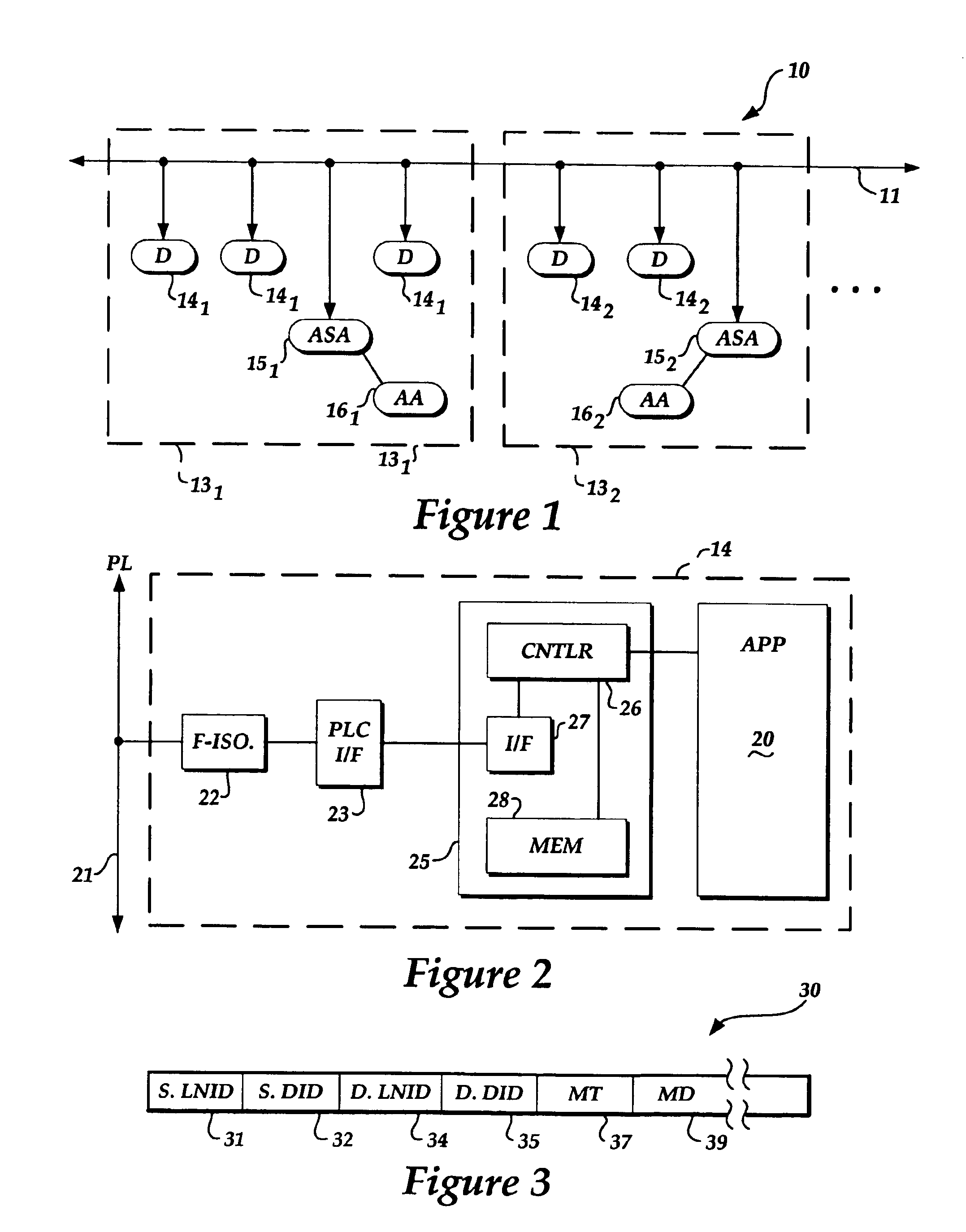
[0019]FIG. 1 illustrates a network 10, according to one embodiment of the present invention. In this embodiment, the network 10 includes a shared media 11 and several logical networks 131, 132 and so on. The network 10 may include any number of logical networks that can be practically coupled to the shared media 11. In one embodiment, the shared media 11 is formed from the power lines of a house, office, factory or other building or buildings. In other embodiments, the shared media can be twisted pair lines, fiber optic lines, telephone lines or coaxial cable lines etc. In still other embodiments, the shared media may be a wireless environment such as, for example, low-power RF and infrared systems. In addition, the shared media can be a combination of two or more of the above media with appropriate interfacing or bridging units.

[0020]In general, each logical network contains one or more devices, an address space arbiter (ASA) and an acquisition authority (AA). Thus, as shown in FIG...


PUM


Abstract

A system for forming and maintaining one or more networks of devices connected to a shared includes processes for: (a) forming a logical network on the shared media; (b) discovering devices connected to the shared medium; (c) assigning (or acquiring) devices to a logical network; and (d) maintaining a logical network. The system also defines a message format and protocol for communication over the shared media. The protocol uses a two-level address scheme (e.g., a logical network ID and a device ID) and defines several message types used to support the above processes and other useful features. A logical network includes an address space arbiter (ASA) and, typically, one or more devices attached to the shared media. An acquisition authority (AA), interacting with the ASA, is required to complete acquisition of a device by a logical network.

Description

BACKGROUND OF THE INVENTION[0001]Many network systems are currently in use in commercial and home environments. For example, computer networks such as the Internet are well known and widely used. The Internet uses the TCP / IP protocol, which requires a significant amount of circuitry and computing power to provide good performance. Of course, such circuitry is relatively costly. On the other hand, some networking applications do not require the high performance of the TCP / IP protocol. One such application is an intelligent home system.[0002]An intelligent home control system requires communication between intelligent household devices in the home system. One approach to implement the communication in an intelligent home control system is to connect devices to a shared medium. However, existing systems tend to provide low performance, support a relatively small number of devices, and require the user to configure devices in forming the network. Further, some conventional systems only ...

Claims


Application Information

Patent Timeline
Patent Type & Authority Patents(United States)
IPC IPC(8): H04L12/66H04L12/28H04L29/08H04L29/12
CPCH04L12/2803H04L12/2809H04L29/12254H04L29/1232H04L29/12801H04L61/2038H04L61/2092H04L61/6004H04L67/16H04L12/2823H04L2012/2843H04L2012/2845H04L2012/2849H04L2012/285H04L61/5038H04L61/5092H04L2101/604H04L67/51
Inventor HASHA, RICHARD L.CHRISTIAN, BRADFORD A.ELSBREE, JOHN E.OSBORNE, TIMOTHY R.
Owner MICROSOFT TECH LICENSING LLC
Learn More