This helps you quickly interpret patents by identifying the three key elements:
Problems solved by technology
Method used
Benefits of technology
Benefits of technology
[0052]Therefore, an object of the present invention is to solve the above problems by providing an AGC apparatus that can achieve a wider dynamic range without impairment of the capabilities of suppressing intermodulation-distortion interference and adjacent-channel interference.
[0055]As described above, in the first aspect, the RF and IF automatic gain controllers are separately controlled. Therefore, it is possible to improve the capabilities of suppressing adjacent-channel interference and intermodulation-distortion interference with a large dynamic range.
[0057]As described above, in the second aspect, the same effects as in the first aspect can be achieved with the dynamic range more varied.
[0059]As described above, in the third aspect, the same effects as in the second aspect can be achieved.
[0063]As described above, in the fifth aspect, in addition to the same effects as in the fourth aspect, influences of variations in quality of the tuner can be reduced.
Problems solved by technology
Such increase disadvantageously causes degradation by 4 dB in the capability of suppressing intermodulation-distortion interference and, in turn, the capability of suppressing adjacent-channel interference.
Such increase disadvantageously causes degradation by 7 dB in capability of suppressing intermodulation-distortion interference.
And, the wider the dynamic range is made, the weaker the capability of suppressing intermodulation-distortion interference becomes, resulting in significant degradation of the capability of suppressing the adjacent-channel interference.
Method used
Image
Click on the blue label to locate the original text in one second.
Reading with bidirectional positioning of images and text.
Examples
first embodiment
[0085]With reference to FIGS. 1, 2, 3, 4, 5, 6, 7, 8, and 9, described below first is an automatic gain control (AGC) apparatus according to the present invention. Then, with reference to FIGS. 10, 11, 12, and 13, described is an AGC apparatus according to a second embodiment of the present invention.
[0086](First Embodiment)
[0087]With reference to FIGS. 1 through 9, described below is the AGC apparatus of the first embodiment. Prior to that, the basic concept of the present invention is first described. In the present invention, an RF automatic gain controller and an IF automatic gain controller are separately controlled. With this control, the present AGC apparatus can improve the capabilities of suppressing intermodulation-distortion interference and adjacent-channel interference with a wide dynamic range.
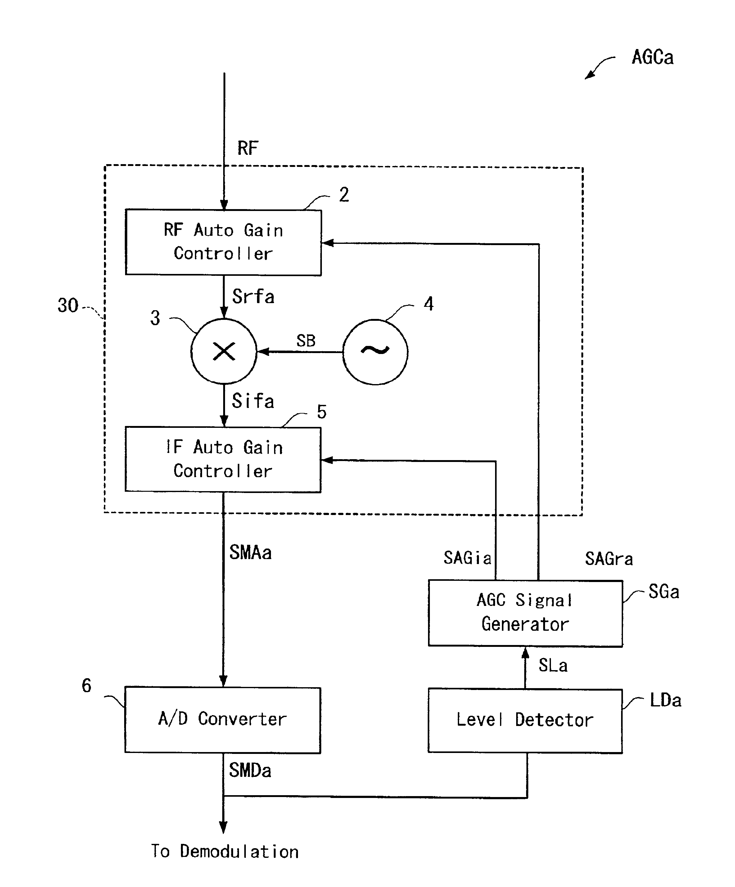
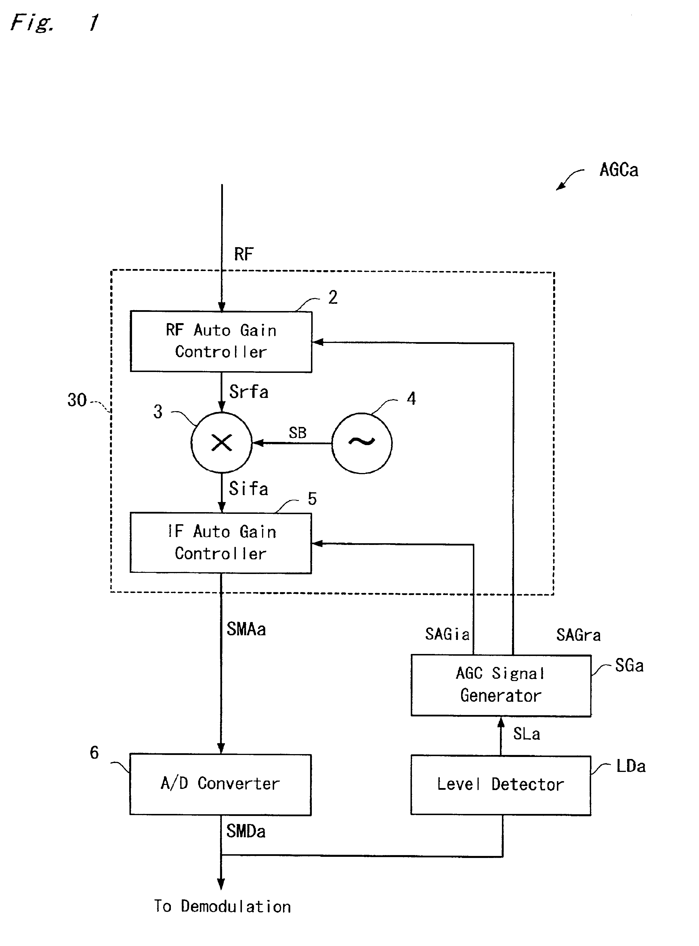
[0088]As shown in FIG. 1, the AGC apparatus AGCa includes a tuner 30, an A / D converter 6, a level detector Lda, and an automatic gain control signal generator (hereinafter, AGC s...
second embodiment
[0134](Second Embodiment)
[0135]With reference to FIGS. 10 and 11, described below is the AGC apparatus of the second embodiment of the present invention. Prior to that, the basic concept of the AGC apparatus according to the second embodiment is first described. The characteristics of the AGC apparatus AGCa according to the first embodiment shown in FIG. 4 can be originally achieved if the parameters X1 and X2 in the above equations (1), (2), (3), (4), (5), (6), (7), (8), (9), and (10) are known. However, in addition to these parameters X1 and X2, the gradients arf and aif, and points of intersection of the RF and IF level signals and the y axis brf and bif are required. Therefore, it is obvious from the equations (4), (5), (9), and (10) that dividers are required.
[0136]As long as these parameters X1, X2, arf, and aif are known, the characteristics shown in FIG. 4 can be achieved without using such dividers. Therefore, if any parameter setting means such as a microcomputer that can ...
BACKGROUND OF THE INVENTION[0001]1. Field of the Invention[0002]The present invention relates to apparatuses for receiving television and radio broadcasting, especially digital broadcasting.[0003]2. Description of the Background Art[0004]Shown in FIG. 14 is the structure of an automatic gain control apparatus (hereinafter referred to as AGC apparatus) conventionally used for a digital broadcast receiving apparatus. The AGC apparatus AGC includes a tuner 30, an A / D converter 6, a level detector LD, and an automatic gain control signal generator (hereinafter, AGC signal generator) SG. The tuner 30 includes an RF automatic gain controller 2 for controlling the gain of a digital broadcast wave RF, a mixer 3, an oscillator 4, an IF automatic gain controller 5 for controlling the gain of an intermediate frequency signal Sif, and an RF gain control pointsetter 40.[0005]In the tuner 30, the RF automatic gain controller 2 carries out automatic gain control and amplification of the digital b...
Claims
Application Information
Patent Timeline
Application Date:The date an application was filed.
Publication Date:The date a patent or application was officially published.
First Publication Date:The earliest publication date of a patent with the same application number.
Issue Date:Publication date of the patent grant document.
PCT Entry Date:The Entry date of PCT National Phase.
Estimated Expiry Date:The statutory expiry date of a patent right according to the Patent Law, and it is the longest term of protection that the patent right can achieve without the termination of the patent right due to other reasons(Term extension factor has been taken into account ).
Invalid Date:Actual expiry date is based on effective date or publication date of legal transaction data of invalid patent.

