One-chip microcomputer and control method thereof as well as an IC card having such a one-chip microcomputer

a one-chip microcomputer and control method technology, applied in the direction of hardware testing methods, error detection/correction, instruments, etc., can solve the problems of increasing the number of terminals of one-chip microcomputers, inability to ensure sufficient quality, and inability to increase the number of exclusively used test terminals

Inactive Publication Date: 2005-08-23
SHARP KK +1
View PDF11 Cites 16 Cited by
  • Summary
  • Abstract
  • Description
  • Claims
  • Application Information

AI Technical Summary

Benefits of technology

[0025]The objective of the present invention is to provide a one-chip microcomputer which can execute a built-in self test without the need for exclusively-used test terminals that cannot be included in its terminals that is limited in number, a controlling method thereof and an IC card equipped with such a one-chip microcomputer.
[0028]With the above-mentioned arrangement or method, a built-in self test is activated (the self test activation circuit, the first step) in accordance with an instruction from the CPU, and output signals of the group of logical circuits and the memory are detected (the self test control circuit, the second step). Therefore, upon completion of the built-in self test, the results of the test are diagnosed based upon the output signals in the one-chip microcomputer in accordance with an instruction from the CPU. In other words, the CPU, built in the one-chip microcomputer, can control the activation of the built-in self test and the diagnosis on the results of the self test.
[0029]Therefore, it is possible to carry out the built-in self test without the need for exclusively-used test terminals that have been conventionally required and for complex control externally given. Since the above-mentioned arrangement or method solves the problem of an increase in the number of terminals in a one-chip microcomputer, it is possible to put the built-in self test into practice even in the case of one-chip microcomputers such as IC cards, which have fewer terminals.
[0033]Since the activation of the built-in self test and the detection of the output signals are controlled by the CPU built in a one-chip microcomputer, it is possible to carry out the built-in self test without the need for exclusively-=used test terminals that have been conventionally required and for complex control externally given.
[0039]Consequently, since the activation of the built-in self test and the detection of the output signals are controlled by the CPU built in the one-chip microcomputer, it is possible to carry out the built-in self test without the need for exclusively-used test terminals that have been conventionally required and for complex control externally given.
[0044]Moreover, the application of a one-chip microcomputer using a JTAG circuit that conforms to the unified standard IEEE1149.1 as a test circuit makes it possible to execute the built-in self test of the IC card by using a control signal of the JTAG circuit. Since the JTAG circuit is a circuit conforming to the unified standard, it is possible to shorten designing and developing periods for one-chip microcomputers using this circuit, and consequently to shorten the developing period for IC cards using these one-chip microcomputers.

Problems solved by technology

As the scale of a one-chip microcomputer becomes greater and complicated, the above-mentioned system for testing functions comes to fail to carry out detections having high failure detection rates, resulting in failure in ensuring sufficient quality.
However, in the above-mentioned conventional arrangement, since the one-chip microcomputer having the built-in self test function requires the exclusively-used test terminals, the resulting problem is an increase in the number of the terminals of the one-chip microcomputer.
For this reason, even through the built-in self test needs to be carried out, it is not practical to increase the number of exclusively-used test terminals so as to carry out the test.

Method used


Image

  • One-chip microcomputer and control method thereof as well as an IC card having such a one-chip microcomputer
  • One-chip microcomputer and control method thereof as well as an IC card having such a one-chip microcomputer
  • One-chip microcomputer and control method thereof as well as an IC card having such a one-chip microcomputer

Examples


embodiment 1

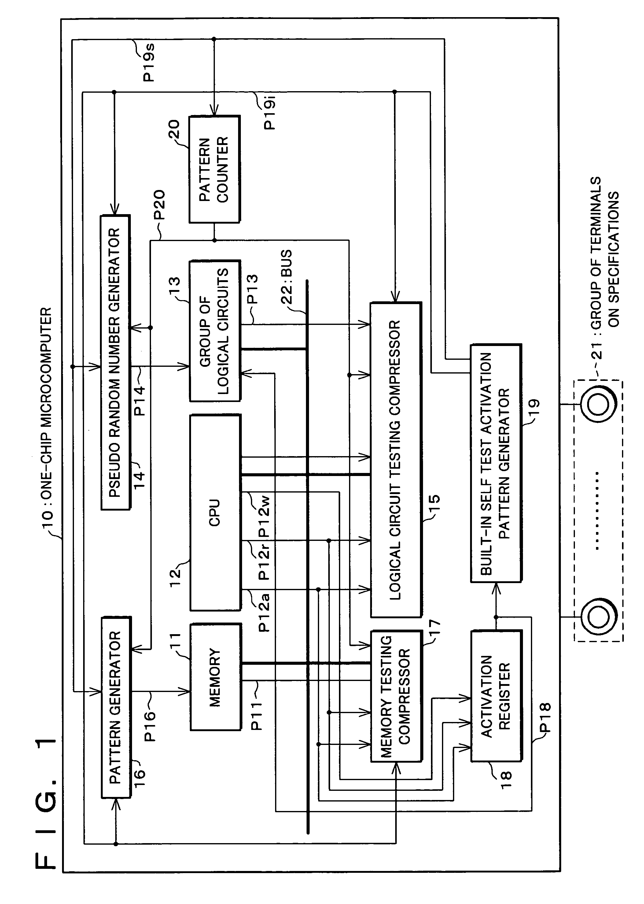
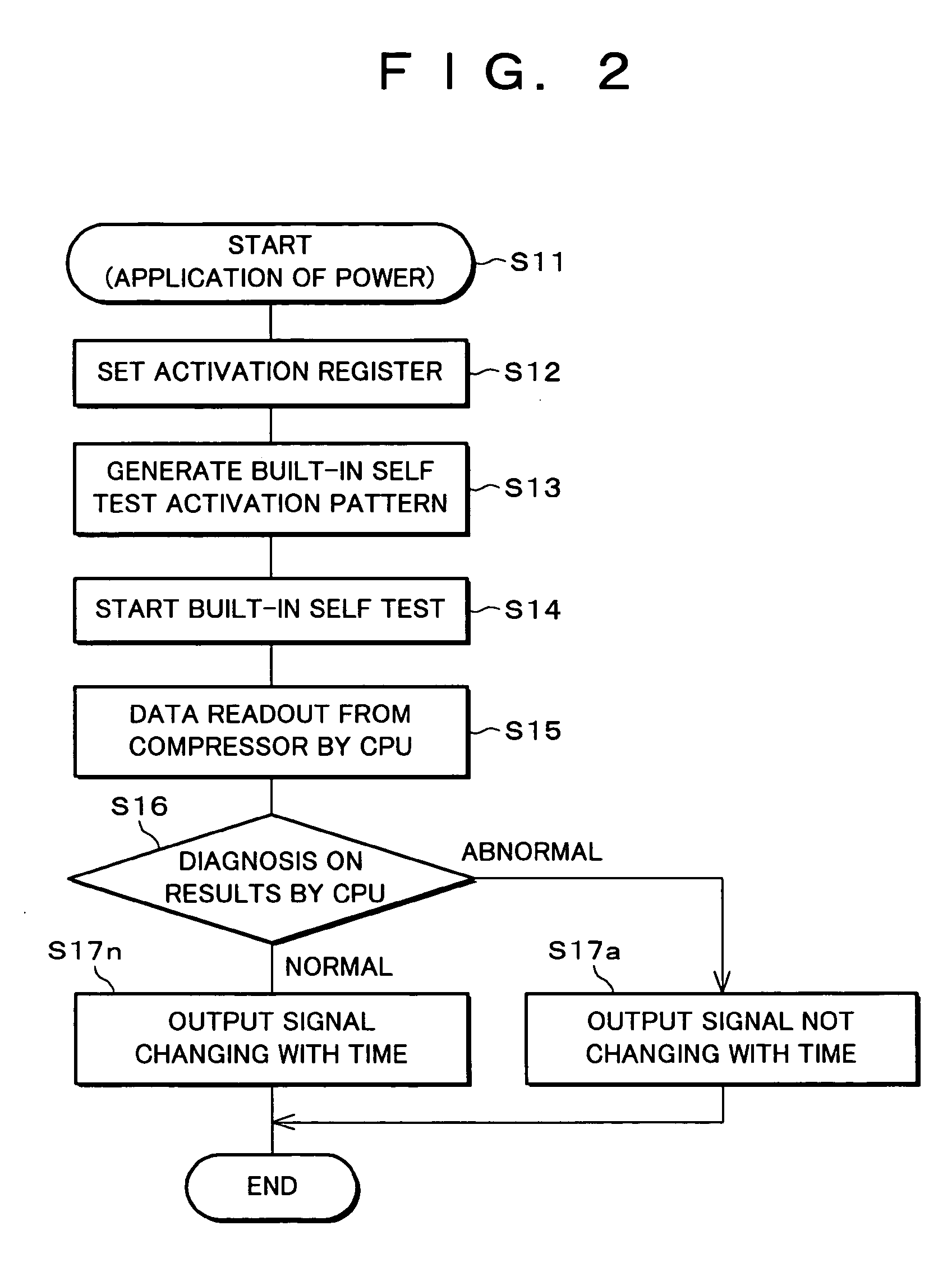
[0060]Referring to FIGS. 1 and 2, the following description will discuss one embodiment of the present invention.

[0061]The one-chip microcomputer of the present invention is provided with a CPU (Central Processing Unit) (Built-in CPU), a memory in which a program for controlling the operation of the CPU is stored and a group of logical circuits, all of which are connected with each other through buses, thereby forming a logical LSI (Large Scale Integrated Circuit) having a built-in self test (BIST: built-in self test) function. Here, the one-chip microcomputer is provided with an activation register for activating a self test control circuit for executing the built-in self test function and a built-in self test activation pattern generator for setting an initial value in the self test control circuit; thus, the CPU is allowed to control the built-in self test on the memory and the group of logical circuits.

[0062]In other words, the one-chip microcomputer of the present embodiment ca...

embodiment 2

[0091]Referring to FIGS. 3 and 4, the following description will discuss another embodiment of the present invention. Here, for convenience of explanation, those members that have the same functions and that are described in embodiment 1 are indicated by the same reference numerals and the description thereof is omitted.

[0092]The one-chip microcomputer of the present embodiment makes it possible to carry out a scan test on the CPU itself which is not available in the one-chip microcomputer in accordance with embodiment 1.

[0093]In the one-chip microcomputer of the aforementioned embodiment 1, when the scan test is carried out on the CPU itself, the following problems arise: (1) The CPU is not allowed to diagnose the test of the memory, (2) it is not allowed to diagnose the scan test of the group of logical circuits, and (3) it is not allowed to diagnose the scan test of the CPU itself. Here, the one-chip microcomputer in accordance with the present embodiment is a test result output ...

embodiment 3

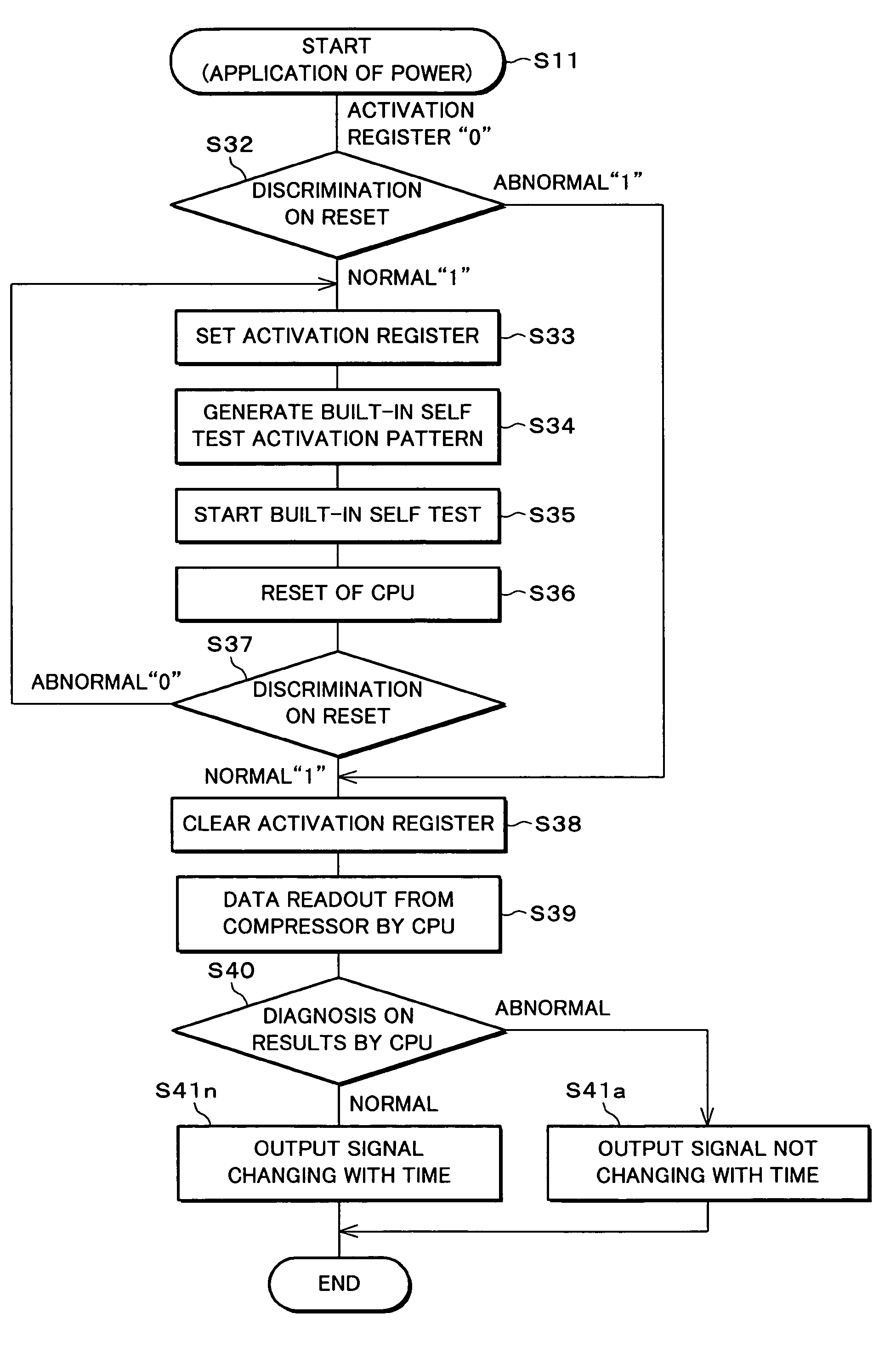
[0108]Referring to FIGS. 5 and 6, the following description will discuss another embodiment of the present invention. Here, for convenience of explanation, those members that have the same functions and that are described in embodiment 1 are indicated by the same reference numerals and the description thereof is omitted.

[0109]The one-chip microcomputer of embodiment 2 carries out the diagnosis outside so as to make it possible to carry out a scan test on the CPU itself. In contrast, the one-chip microcomputer of the present embodiment also makes it possible to carry out the scan test on the CPU itself, and the CPU is also allowed to diagnose the results of the test.

[0110]More specifically, the one-chip microcomputer of the present embodiment is provided with a reset generator for initializing the built-in CPU, and upon completion of the built-in self test, the built-in CPU is reset so that the CPU is again allowed to operate in accordance with the program stored in the memory. With ...


PUM


Abstract

In order to provide a built-in self testing function, a one-chip microcomputer is equipped with an activation register for activating the test operation and a built-in self test activation pattern generator for setting initial values at test control circuits (pseudo random number generator, logical circuit testing compressor, pattern generator, and memory testing compressor). In accordance with an instruction from the CPU, a built-in self test is activated so that the results of tests of the memory and the group of logical circuits are read from the memory testing compressor and the logical circuit testing compressor, and respectively compared with expected values preliminarily stored in the memory in the one-chip microcomputer; thus, the results are diagnosed. Thus, it is possible to carry out a built-in self test without using a plurality of exclusively-used test terminals.

Description

FIELD OF THE INVENTION[0001]The present invention relates to a test circuit for a one-chip microcomputer, and more particularly concerns a one-chip microcomputer provided with a built-in self test circuit in which a built-in CPU carries out the activation of the built-in self test and diagnosis on the results and a controlling method therefor, as well as an IC card equipped with such a microcomputer.BACKGROUND OF THE INVENTION[0002]One of the test systems for a group of logical circuits in a one-chip microcomputer is a system for inspecting its functions. This is a test system for checking to see whether or not the one-chip microcomputer satisfies specifications assumed by the designer, in which the operation is traced in accordance with its specifications.[0003]As the scale of a one-chip microcomputer becomes greater and complicated, the above-mentioned system for testing functions comes to fail to carry out detections having high failure detection rates, resulting in failure in en...

Claims


Application Information

Patent Timeline
Patent Type & Authority Patents(United States)
IPC IPC(8): G01R31/3183G01R31/28G06F11/22G06F11/267G06K19/07G06F11/26G06F15/78
CPCG01R31/318335G01R31/318385G01R31/318392G06F11/2236G06F11/2273G06F11/26
Inventor WAKABAYASHI, MASAKIYAEGAWA, KAZUHIROTANNO, MASAAKISUTO, HIROKITAKEDA, TADAO
Owner SHARP KK
Why Eureka
Try Eureka