
Method and apparatus for flaring a tube

Inactive Publication Date: 2005-08-30
COMMSCOPE TECH LLC
View PDF9 Cites 19 Cited by
  • Summary
  • Abstract
  • Description
  • Claims
  • Application Information

AI Technical Summary

Benefits of technology

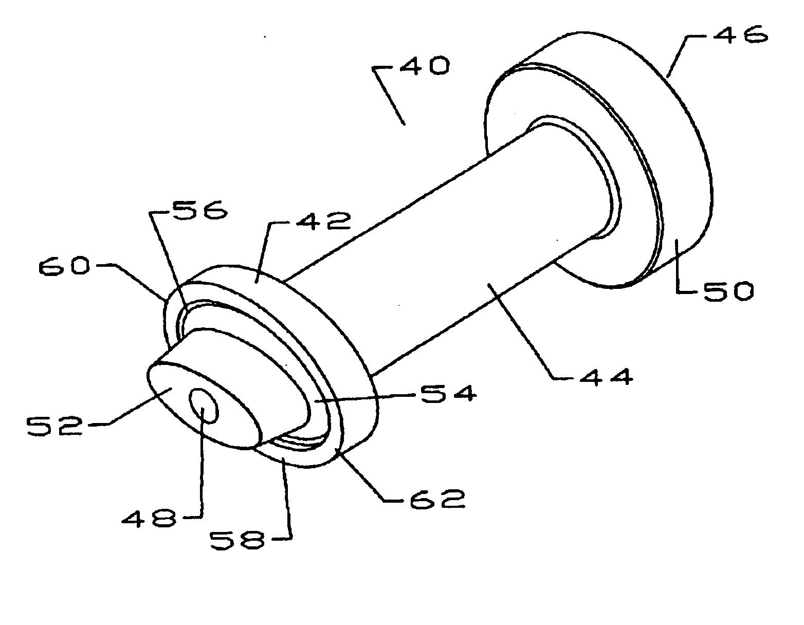
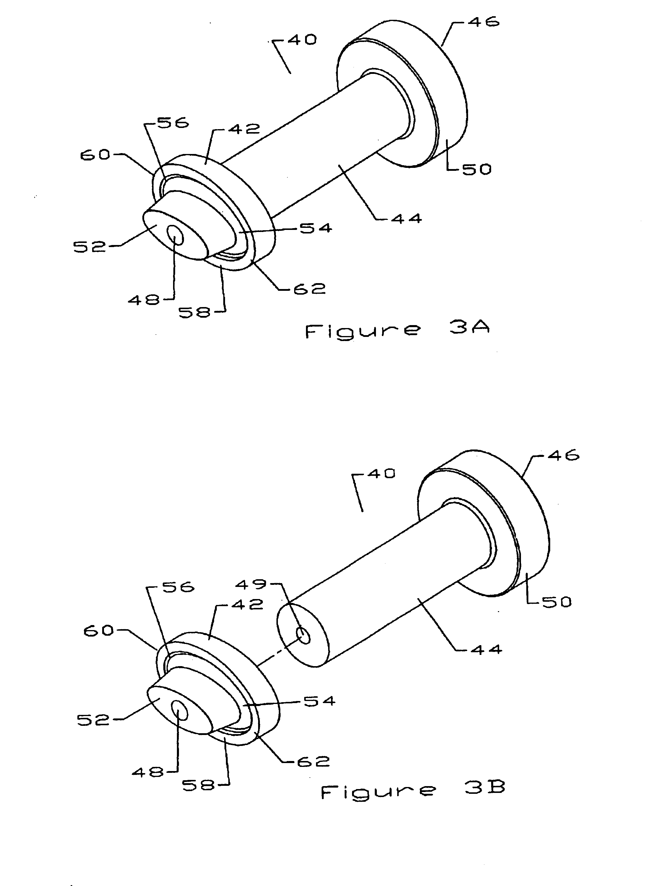
[0018]In accordance with the present invention, the flare 16 on the end of the elliptical tube 15 may be formed by a flare tool 40 as shown in FIGS. 3A and 3B. The flare tool has a die head 42, a retaining portion 44 and an impact surface 46. Different die heads 42 may be adapted to specific waveguides 14 having, for example, different dimensions and or corrugation configurations. The desired die head 42 may be formed integrally with the retaining portion 44 and impact surface 46 or securely coupled to the retaining portion 44 via, for example, a screw threaded into a hole 48. The retaining portion is dimensioned, for example, to be securely grasped by a typical user's hand. The impact surface 46 may include a guard 50 having an increased radius relative to the retaining portion 44, useful for protecting the user's hand while a hammer or other impact device is struck upon the impact surface 46.
[0023]The angle of the bottoming surface 58 is selected to fall within a range having two constraints. First, the angle is large enough to engage and direct the inwardly projecting corrugation outwards, rather than collapsing and or folding it inward. Second, the angle of the bottoming surface 58 is limited so that, when the die head 42 is bottomed against a completed flare, the guide plug 52 is not driven against the internal walls of the waveguide 14 causing a deformation thereof. To minimize this aspect, the guide plug 52 may be provided with an outer edge taper which is large enough to prevent damage to the interior surface of the waveguide 14 when the bottoming surface 58 is flush with the compression ring 24, but not so large that the guide plug 52 looses its keying function. The bottoming surface 58 angle may be approximately one half of the corrugation pitch angle. The corrugation pitch angle being the angle of the helical corrugations with respect to a reference plane normal to the longitudinal axis of the waveguide 14.
[0026]a new and improved method and apparatus for forming a flare 16 on the end of an elliptical tube 15, without requiring repeated working of the metal. The flare 16 that is formed is of substantially uniform thickness so as to enable the flare 16 to make good electrical contact with the waveguide connector 20. As described, the invention provides an inexpensive, portable and reliable means for forming a high quality flare 16 on an elliptical tube 15, with reduced time and user training requirements.

Problems solved by technology

When these flare tools are used with elliptical cross-section tubing having helical corrugations, the tubing end must be repeatedly worked and or hammered, making it difficult to prepare an acceptable flare without a considerable time investment by a skilled metalworker.
The presence of helical corrugations on the tube further complicates formation of an acceptable flare.
Previously available flare tools designed specifically for forming flares in elliptical tubing have been relatively expensive and require separate time consuming operations with a plurality of tools to form an acceptable flare.
Competition within the waveguide industry has focused attention on equipment and personnel costs, as well as time requirements for installation and maintenance of waveguide systems.

Method used


Image

  • Method and apparatus for flaring a tube
  • Method and apparatus for flaring a tube
  • Method and apparatus for flaring a tube

Examples


Embodiment Construction

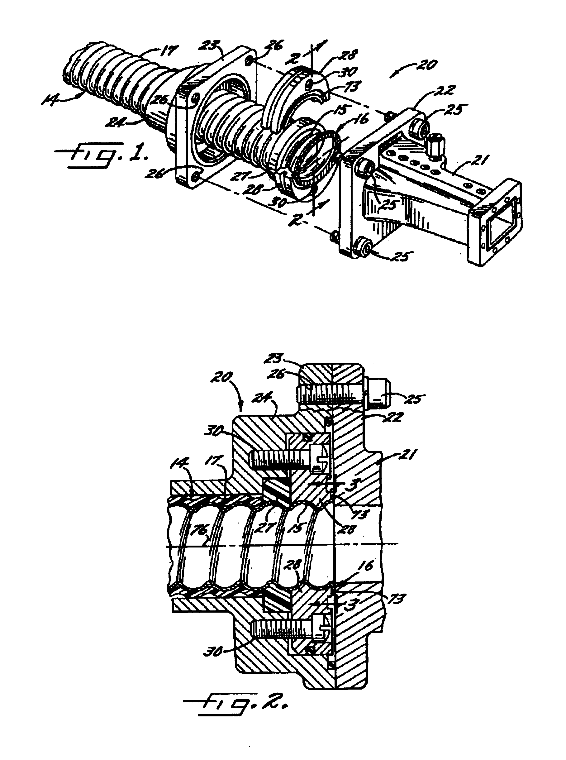
[0016]For purposes of illustration, a typical use of the present invention, forming connections in a waveguide system, is shown in FIG. 1. The waveguide 14 is of the type used, for example, to carry a signal in a microwave antenna feeder system. The waveguide 14 comprises a corrugated tube 15, for example made of copper or other conductive metal, having an elliptical cross-section. A sheath 17 of insulating material encapsulates the length of the tube. The sheath 17 is removed where electrical connection to the waveguide 14 is desired. The end of the corrugated tube 15 is formed with an outwardly extending end flare 16 through application of the present invention.

[0017]A waveguide connector 20 is coupled to the end portion of the tube 15 to couple the waveguide 14 to, for example, an antenna feed horn or the like. In this instance, the waveguide connector 20 has an elliptical to rectangular transition body 21 formed with a mounting flange 22 adapted to be fastened to the flange 23 o...


PUM

PropertyMeasurementUnit
Fractionaaaaaaaaaa
Angleaaaaaaaaaa
Radiusaaaaaaaaaa

Abstract

A tool for forming flares in, for example, corrugated elliptical tubing. The tool may have a retaining portion having a longitudinal axis located between an impact surface and a die head. The die head is coupled to the retaining portion on a first side, and on a second side the die head has a guide plug extending from an inner area of a flare surface normal to the longitudinal axis; and a bottoming surface extending from a periphery of the flare surface. The bottoming surface is oriented at an angle to the flare surface. A saw guide may be used to obtain an appropriate extension of the tube from a stop which the flare is formed against.

Description

BACKGROUND OF INVENTION[0001]1. Field of the Invention[0002]This invention relates to the formation of an external flare around the end of a metal tube. More particularly, the invention is concerned with flaring the end of a tube of substantially elliptical cross-section having helical corrugations along its length.[0003]2. Description of Related Art[0004]Elliptical tubes having helical corrugations are widely used as waveguides in the RF / microwave industry. When the elliptical tube is used as a waveguide, the end may be flared to, for example, squarely abut a waveguide connector or splice in order to establish electrical contact between the waveguide and the connector or splice. To enable good electrical contact between the waveguide and the connector or splice, it is desirable for the flare to be free of cracks and of substantially uniform thickness.[0005]Prior screw press and or hammer type flare tools are typically intended for use with tubular tubing, for example electrical con...

Claims


Application Information

Patent Timeline
IPC IPC(8): F16L25/00F16L33/26
CPCF16L25/0036F16L33/26
Inventor FRIGO, GARYTHAVISOUK, BOUNTHAVYMCCARTHY, JOHN
Owner COMMSCOPE TECH LLC
Learn More