Exhaust-gas recirculation system of an internal combustion engine

a technology of exhaust gas and internal combustion engine, which is applied in the direction of machines/engines, mechanical equipment, and non-fuel substance addition to fuel, can solve the problems of low cooling capacity of the first exhaust-gas cooler, and achieve the effects of preventing overheating and excessive corrosion, reducing cooling capacity, and improving the cooling capacity of the second exhaust-gas cooler

Inactive Publication Date: 2005-08-30
DAIMLER AG
View PDF10 Cites 38 Cited by
  • Summary
  • Abstract
  • Description
  • Claims
  • Application Information

AI Technical Summary

Benefits of technology

[0005]As a result, in motor vehicles with an engine-braking mode or with an exhaust-gas conduction system that can be blocked, the second exhaust-gas cooler is not subjected to high exhaust-gas pressures when the exhaust-gas recirculation valve is closed. The first exhaust-gas cooler, which is arranged upstream of the exhaust-gas recirculation valve with respect to the direction of flow, prevents an overheating and excessive corrosion of the exhaust-gas recirculation valve. The exhaust-gas recirculation valve can thus be arranged within the exhaust-gas recirculation line optimally within the available construction-space conditions and the existing temperature conditions. The exhaust-gas cooling additionally necessary for optimum combustion is achieved by means of the second exhaust-gas cooler, which is arranged downstream of the exhaust-gas recirculation valve and is not exposed to high temperatures and high pressures.
[0006]For this purpose, the first exhaust-gas cooler is designed as a pressure- and temperature-resistant cooler. This ensures that the load peaks during the engine-braking mode do not result in damage to the first exhaust-gas cooler. The greater wall thickness necessary in this case however leads to a lower cooling capacity of the first exhaust-gas cooler.
[0007]The second exhaust-gas cooler is designed as a low-pressure cooler, which requires walls of only a relatively small thickness. This results, according to the smaller wall thickness with the same construction size, in an improved cooling capacity of the second exhaust-gas cooler and lower exhaust gas temperatures and consequently, overall, in an optimized combustion process.
[0008]It is also advantageous, in this regard, if at least one further exhaust-gas cooler is provided upstream of the exhaust-gas recirculation valve with respect to the direction of flow. According to the available space conditions, the necessary cooling capacity between the exhaust-gas manifold and the exhaust-gas recirculation valve can be ensured by means of a plurality of small coolers rather than one relatively large cooler.
[0009]It is advantageous for the present invention if the inlet and the outlet the exhaust-gas recirculation valve are arranged on a common lateral surface of the exhaust-gas recirculation valve. The exhaust-gas recirculation line may then extend from the first exhaust gas cooler to one side of the exhaust-gas recirculation valve and extend from the same side of the exhaust-gas recirculation valve back to the second exhaust gas cooler. This results in a deflection of the exhaust-gas recirculation line, which is suitable for the available design-space conditions.
[0010]It is also advantageous if the charge-air cooler, the first exhaust-gas cooler and / or the second exhaust-gas cooler have a common cooling circuit. The temperature level of the coolers can thereby be taken into account: The coolant, after passing through the charge-air cooler, can still be utilized for cooling the first exhaust-gas cooler on the hot side of the exhaust-gas recirculation valve, since the existing temperature difference ensures sufficient cooling capacity.

Problems solved by technology

The greater wall thickness necessary in this case however leads to a lower cooling capacity of the first exhaust-gas cooler.

Method used


Image

  • Exhaust-gas recirculation system of an internal combustion engine
  • Exhaust-gas recirculation system of an internal combustion engine

Examples


Embodiment Construction

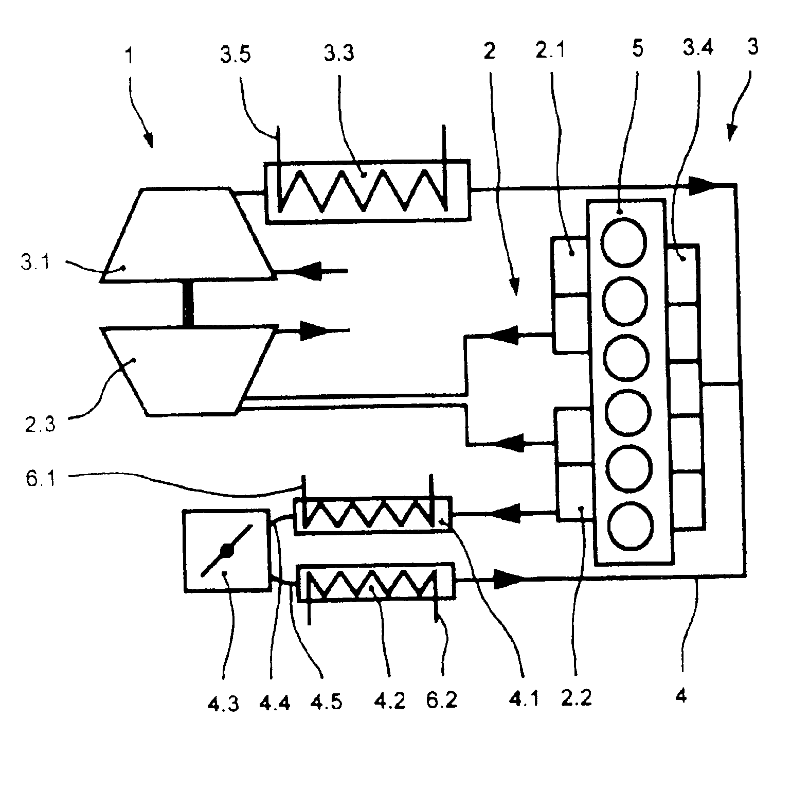
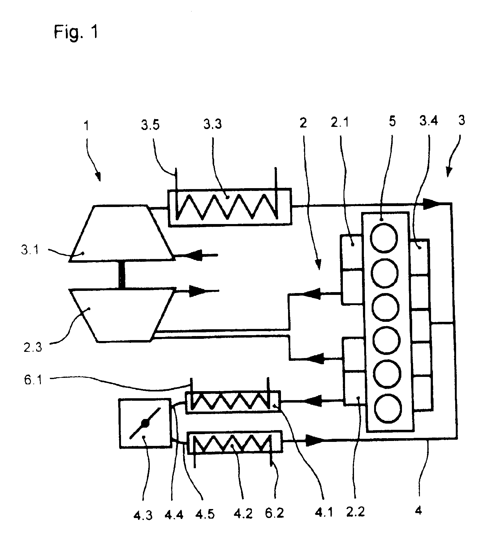
[0013]FIG. 1 illustrates an internal combustion engine, an air inlet system 3 and an exhaust-gas discharge system 2, of the internal combustion engine, which includes a cylinder block 5. The exhaust-gas discharge system 2 is connected to the cylinder block 5 via a first exhaust-gas manifold 2.1 and a second exhaust-gas manifold 2.2. The exhaust-gas discharge system 2 extends from the first exhaust-gas manifold 2.1 or from the second exhaust-gas manifold 2.2 to an exhaust-gas turbine 2.3.

[0014]The exhaust-gas turbine 2.3 serves as a motor for a charge-air compressor 3.1, via which charge air is supplied to the air inlet system 3. The air inlet system 3 includes a charge-air cooler 3.3 which, in turn, is connected to a charge-air manifold 3.4 on the cylinder block 5.

[0015]Connected to the second exhaust-gas manifold 2.2, is an exhaust-gas recirculation line 4, which is connected at its other end, together with the air inlet system 3, to the charge-air manifold 3.4. The exhaust-gas rec...


PUM


Abstract

In an exhaust-gas recirculation system of an internal combustion engine with an exhaust-gas recirculation line extending between an exhaust duct and an inlet duct, wherein the exhaust-gas recirculation line includes an exhaust-gas recirculation valve and also at least one first exhaust-gas cooler, at least one second exhaust-gas cooler is provided in the exhaust gas recirculation line and the exhaust-gas recirculation valve is arranged between the first exhaust-gas cooler and the second exhaust-gas cooler so that only the first exhaust gas cooler is subjected to the high exhaust gas pressure effective during engine braking when the exhaust gas recirculation valve is closed.

Description

BACKGROUND OF THE INVENTION[0001]The invention relates to an exhaust-gas recirculation system for motor vehicles, with an exhaust-gas recirculation line extending between an exhaust-gas duct and an inlet duct and including an exhaust-gas recirculation valve and at least one exhaust-gas cooler.[0002]An exhaust-gas recirculation system for motor vehicles is already known from EP 0 596 855 A1. The exhaust-gas recirculation line, in this case, has an exhaust-gas recirculation valve and an exhaust-gas heat exchanger arranged downstream of the exhaust-gas recirculation valve with respect to the direction of flow. Moreover, an exhaust-gas purification device is arranged between the exhaust-gas recirculation valve and the exhaust-gas heat exchanger.[0003]It is the object of the present invention to provide an exhaust-gas recirculation system, which achieves optimum cooling of the exhaust gases and high durability of the system at relatively low costs.SUMMARY OF THE INVENTION[0004]In an exha...

Claims


Application Information

Patent Timeline
Patent Type & Authority Patents(United States)
IPC IPC(8): F02M25/07F02B29/04F02B29/00
CPCF02M25/0707F02M25/0732F02M25/0749F02B29/0437F02M25/0731Y02T10/121F02M26/43F02M26/05F02M26/28F02M26/24
Inventor AUPPERLE, WALTERKALISCH, PETER
Owner DAIMLER AG
Why Eureka
Try Eureka