Stent delivery system having a fixed guidewire

a technology of a guidewire and a fixed wire, which is applied in the field of stent delivery systems having a fixed guidewire, can solve the problems of additional procedure time for placing the guidewire, and achieve the effects of saving the cost of the guidewire, and reducing the probability of any kinking of the core wir

Inactive Publication Date: 2005-08-30
WYETH LLC
View PDF12 Cites 97 Cited by
  • Summary
  • Abstract
  • Description
  • Claims
  • Application Information

AI Technical Summary

Benefits of technology

[0006]One embodiment of the present invention uses a core wire that extends for the entire length of the stent delivery system. This core wire is also centrally located in the fixed guidewire that extends from the distal end of the balloon onto which the stent is mounted. Although this core wire can be made from a conventional metal such as stainless steel, the use of shape memory metal alloys (such as the nickel titanium alloy known as Nitinol) is ideal for such a core wire.
[0007]Furthermore, in a preferred embodiment of this invention , the Nitinol used for the fixed guidewire portion of the stent delivery system should have a transition temperature that is greater than body temperature. Therefore, prior to insertion, the interventional cardiologist who inserts the stent delivery system can make an appropriate bend into the end of the guidewire in order to maneuver the end of the guidewire into a specific artery. If the guidewire becomes damaged in passing through some difficult vasculature, the present invention describes the use of a special heater that can then be used to heat the guidewire to a temperature above its transition temperature, so that the guidewire would have its pre-damaged shape restored. Typically, the pre-damaged state would be a substantially straight wire or a wire with a slight, pre-set bend. After the guidewire cools below body temperature, the guidewire could then be reshaped again by the interventional cardiologist, to once again try to navigate through some tortuous part of the vasculature.
[0008]In a Nitinol implementation of the core wire of the stent delivery system, most of the core wire that lies proximal to the proximal end of the guidewire should have a transition temperature below body temperature. Therefore, the superelastic properties of the Nitinol core wire proximal section will greatly reduce the probability of any kinking of the core wire that might occur if the metal were stainless steel.
[0009]Another embodiment of the present invention has a core wire that extends for nearly the entire length of the stent delivery system, the guidewire having different levels of stiffness for different portions of the core wire's length. For example, the proximal section should be extremely “pushable” would be the most stiff. The portion that lies within the balloon expandable stent should be very flexible, since the stent would be able to provide the needed “pushability”. The present invention envisions that the variations in stiffness may be accomplished by changing the diameter of the core wire or by using different materials for different sections of the core wire.
[0010]Thus an object of the present invention is to provide a means for placing a stent within a vessel of the human body without requiring a separate guidewire, thus saving the cost of the guidewire and also saving the time required to place a separate guidewire through an obstruction such as an arterial stenosis.
[0011]Another object of the present invention is to reduce the outside diameter (i.e., the profile) of the distal section of the stent delivery system so as to optimize the capability of the stent delivery system for direct stenting.

Problems solved by technology

Placing the guidewire requires additional procedure time.

Method used


Image

  • Stent delivery system having a fixed guidewire
  • Stent delivery system having a fixed guidewire
  • Stent delivery system having a fixed guidewire

Examples


Embodiment Construction

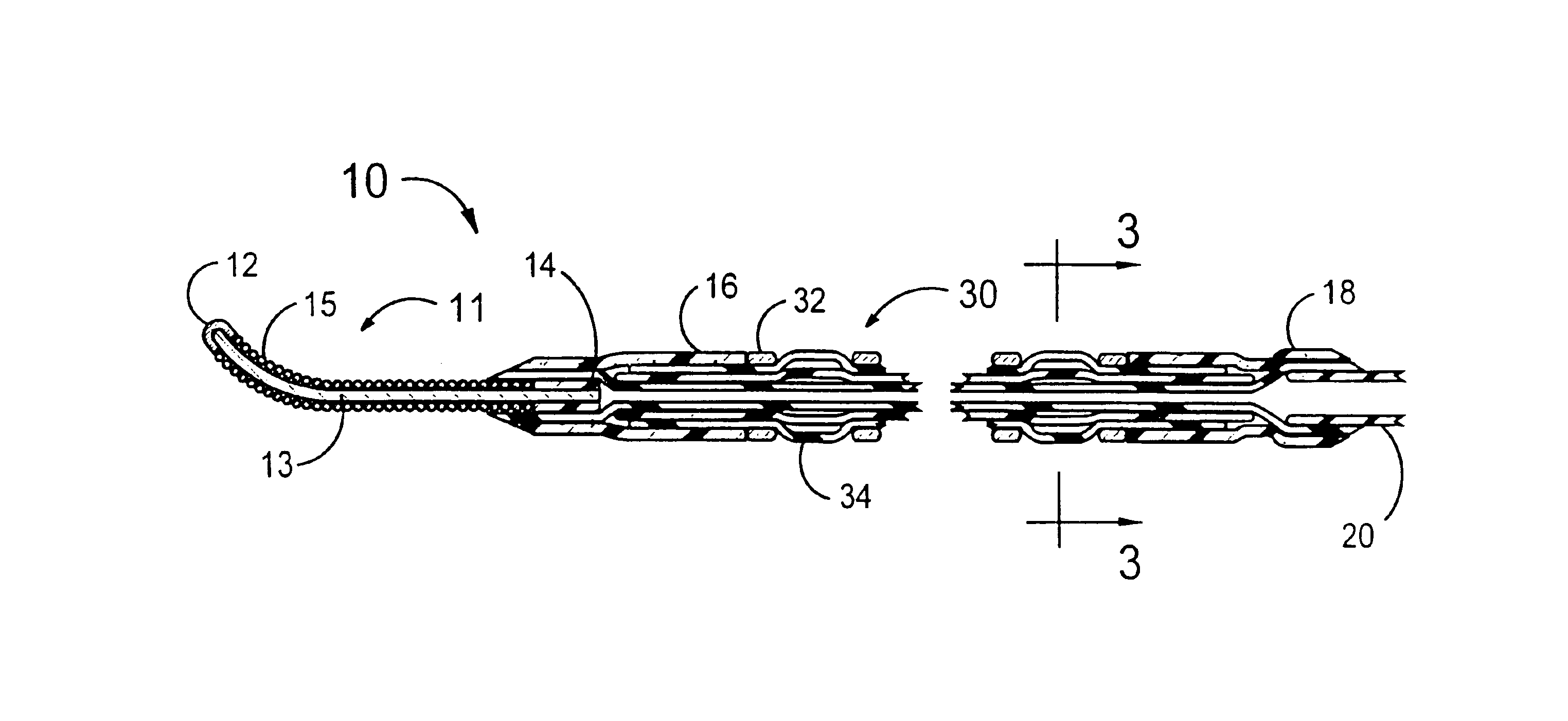
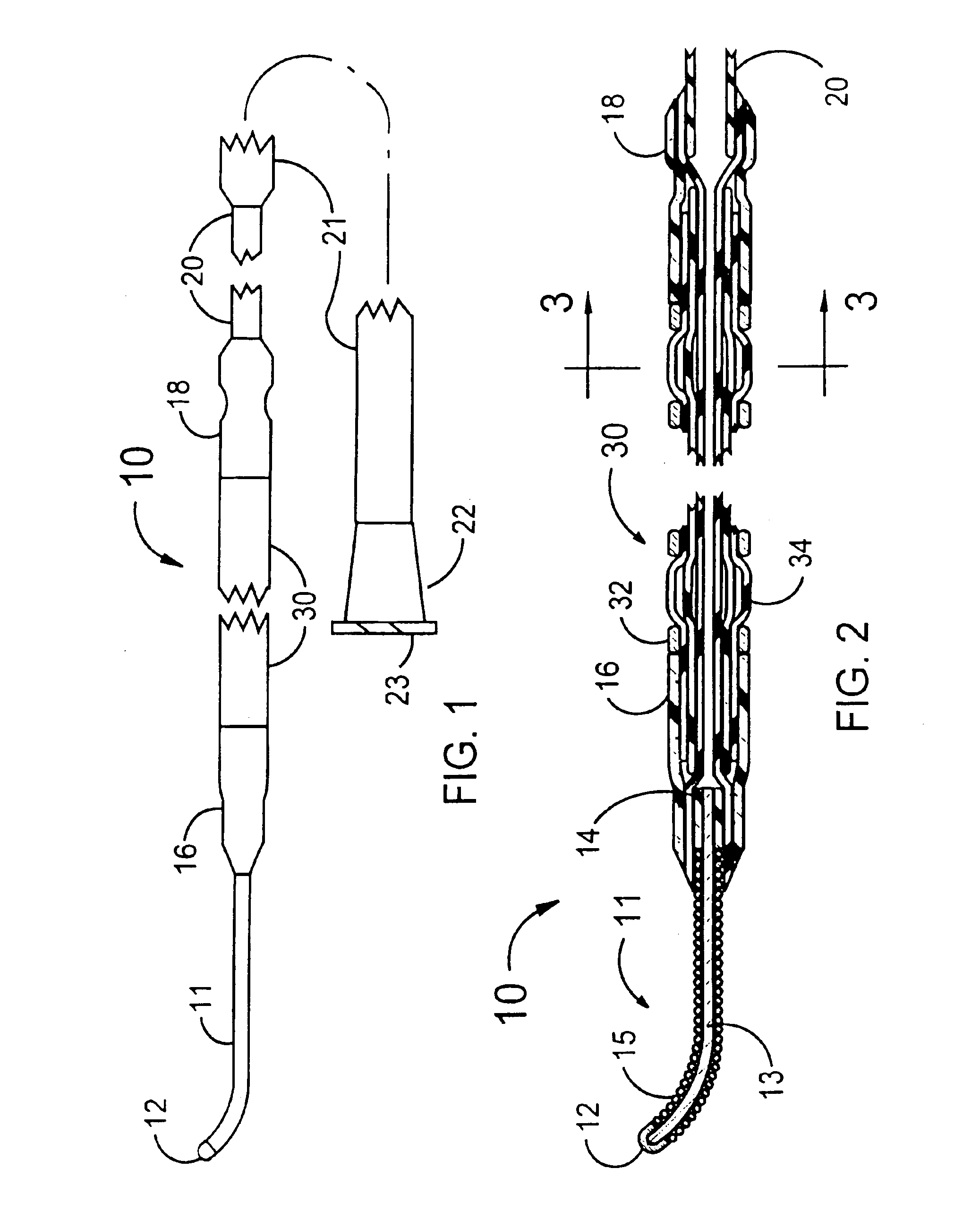
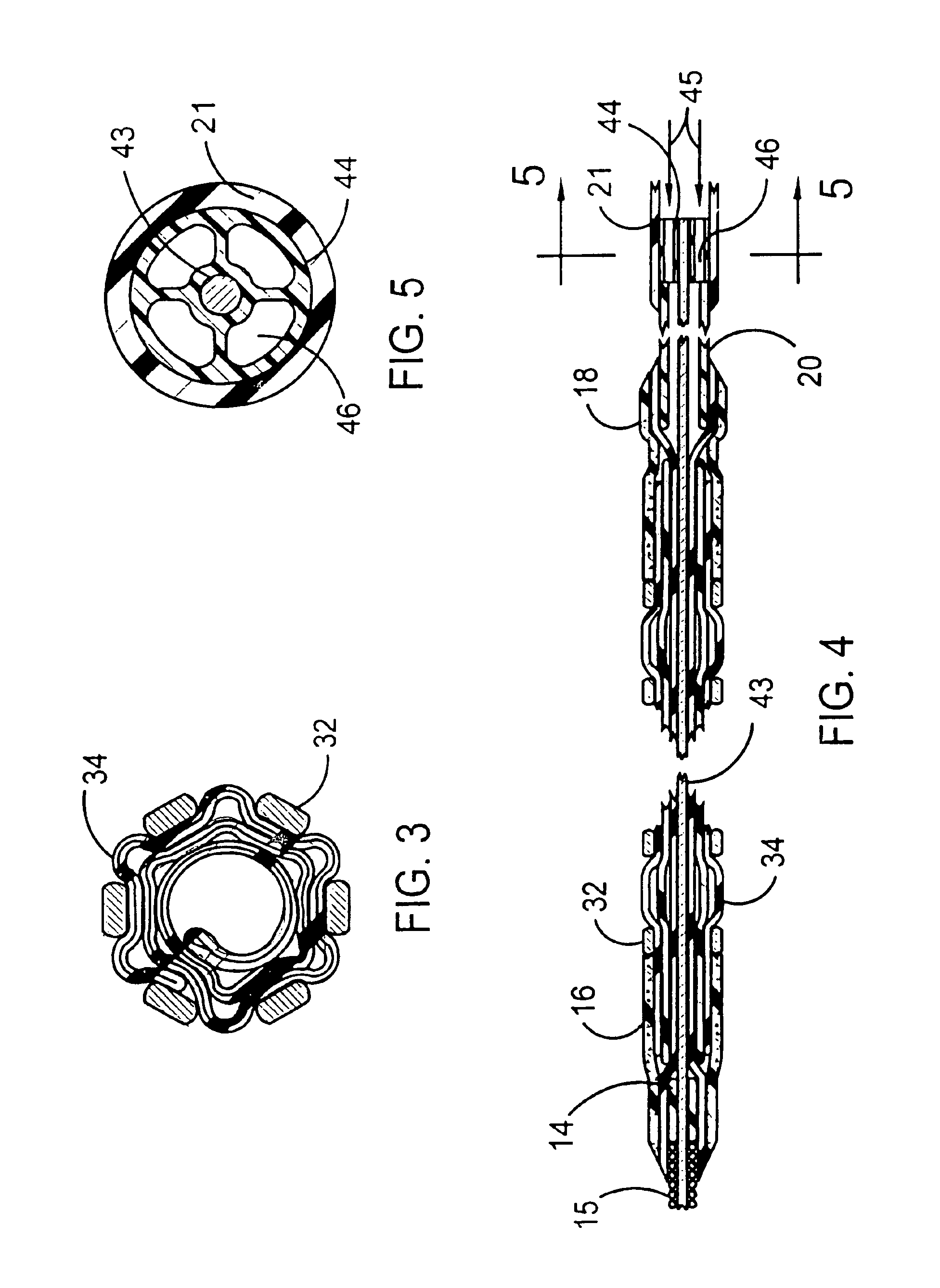
[0027]FIGS. 1 and 2 illustrate a stent delivery system 10 having a fixed guidewire 11 that is fixedly attached to the distal end of a balloon angioplasty catheter that has a minimum profile for the distal section of the balloon angioplasty catheter. The distal section of the stent delivery system 10 includes a guidewire 11, a proximal elastic band 18, a stent-on-balloon section 30 and a distal elastic band 16. The stent-on-balloon section 30 includes an inflatable balloon 34 onto which a balloon expandable stent 32 is co-axially mounted. A cylindrically shaped distal section of the balloon 34 is fixedly attached to a proximal section of the guidewire 11 that includes a plastic cylinder 14 that is fixedly attached to a central core wire 13 of the guidewire 11.

[0028]A helical wire coil 15 is wrapped around the core wire 13 for most of the length of the core wire 13. The outside diameter of the guidewire 11 would typically be 0.014 inches. However, outside diameters between 0.008 and 0...


PUM


Abstract

The present invention is a stent delivery system that uses short section of guidewire fixedly attached to the distal section of a balloon angioplasty catheter onto which a stent is co-axially mounted. By not having a guidewire that slides through the balloon of the balloon angioplasty catheter, the deflated balloon on which the stent is mounted can have a reduced diameter. Therefore, the outer diameter of the pre-deployed stent mounted onto that balloon is also minimized. This provides a smaller profile, i.e., a smaller outer diameter, for the stent. The time to perform a stent delivery procedure is reduced; a separate guidewire does not have to be placed prior to using the stent delivery system to place the stent at the site of a stenosis. Another embodiment of the present invention has a core wire that extends for nearly the entire length of the stent delivery system, the guidewire having different levels of stiffness for different portions of the core wire's length.

Description

REFERENCE TO PRIOR APPLICATION[0001]This application is a continuation-in-part of U.S. patent application Ser. No. 09 / 444,104 filed on Nov. 22, 1999 now U.S. Pat. No. 6,375,660, and Ser. No. 10 / 107,221, filed Mar. 26, 2002, pending.FIELD OF USE[0002]This invention is in the field of devices for percutaneous insertion into a vessel of the human body to place a stent at the site of an obstruction.BACKGROUND OF THE INVENTION[0003]Stents are well known devices for placement in vessels of the human body to obtain and maintain patency of that vessel. The greatest use for stents has been for placement within a stenosis in a coronary artery. When a stent is used for treating a coronary artery stenosis, it has always been necessary to first place a guidewire through the stenosis. The next step in the stenting procedure may be to pre-dilate the stenosis with a balloon angioplasty catheter that is advanced over that guidewire. The catheter may be of the over-the-wire or rapid exchange variety....

Claims


Application Information

Patent Timeline
Patent Type & Authority Patents(United States)
IPC IPC(8): A61F2/06A61F2/84
CPCA61F2/95A61F2/958A61M2025/0186A61M2025/1004
Inventor KHAN, I. JOHNBURGERMEISTER, ROBERTFISCHELL, ROBERT E.FISCHELL, DAVID R.
Owner WYETH LLC
Why Eureka
Try Eureka