Fuel cell stack
- Summary
- Abstract
- Description
- Claims
- Application Information
AI Technical Summary
Benefits of technology
Problems solved by technology
Method used
Image
Examples
first embodiment
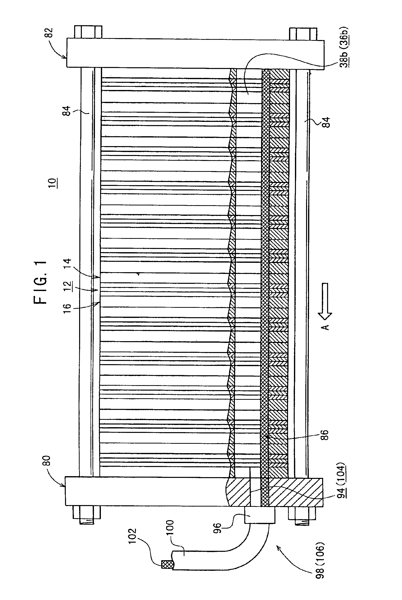
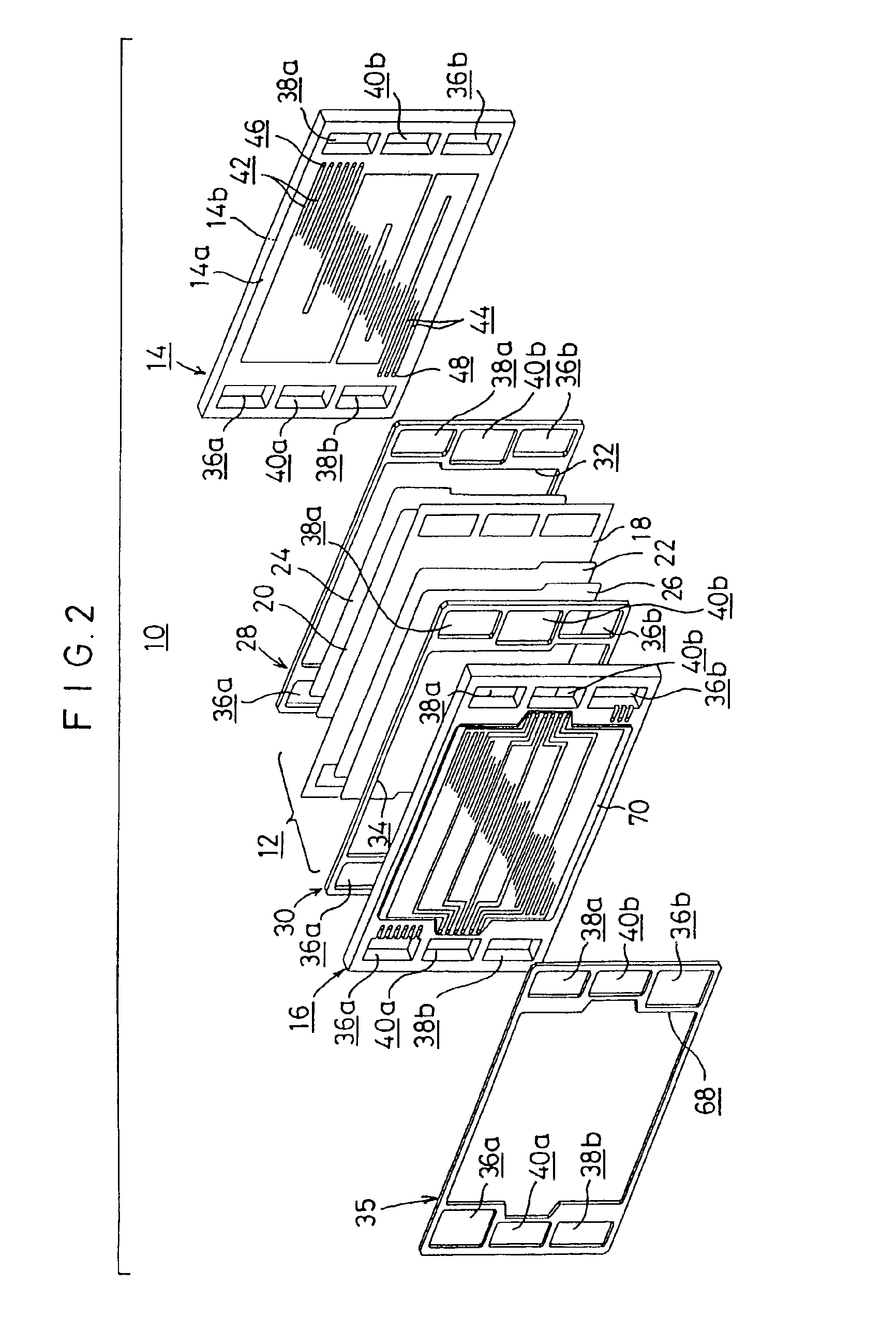
[0046]FIG. 1 shows a schematic longitudinal sectional view illustrating a fuel cell stack 10 according to the present invention, and FIG. 2 shows an exploded perspective view illustrating major components of the fuel cell stack 10 described above.
[0047]The fuel cell stack 10 comprises a fuel cell unit 12, and first and second separators 14, 16 for supporting the fuel cell unit 12 interposed therebetween. A plurality of sets of these components are stacked with each other. The fuel cell unit 12 includes a solid polymer ion exchange membrane 18, and a cathode electrode 20 and an anode electrode 22 which are arranged with the ion exchange membrane 18 intervening therebetween. First and second gas diffusion layers 24, 26, each of which is composed of, for example, porous carbon paper as a porous layer, are arranged for the cathode electrode 20 and the anode electrode 22.
[0048]First and second gaskets 28, 30 are provided on both sides of the fuel cell unit 12. The first gasket 28 has a l...
fifth embodiment
[0085]FIG. 13 shows a longitudinal sectional view illustrating a fuel cell stack 160 according to the present invention. In the fuel cell stack 160, porous water-absorbing tubes 162 are arranged for the outlet side oxygen-containing gas communication hole 38b and the outlet side fuel gas communication hole 36b. The porous water-absorbing tube 162 comprises a pipe member 164 and a plurality of wire members 166 arranged at the inside of the pipe member 164.
[0086]The pipe member 164 is provided with a plurality of holes 168 which are formed at portions to be arranged at the outlet side oxygen-containing gas communication hole 38b and the outlet side fuel gas communication hole 36b, making it possible to effect the permeation of water. On the other hand, no hole is provided at the portion exposed to the outside of the fuel cell stack 160. The pipe member 164 is constructed in an integrated manner. However, it is also preferable that a tube provided with the holes 168 and a tube having n...
sixth embodiment
[0087]FIG. 14 shows a vertical sectional view illustrating a porous water-absorbing tube 180 which constitutes a fuel cell stack according to the present invention. The porous water-absorbing tube 100 comprises a water-absorbing member 182 having a solid cross section which is embedded on the lower side in the direction of the gravity of each of the outlet side oxygen-containing gas communication hole 38b and the outlet side fuel gas communication hole 36b. The water-absorbing member 182 is composed of, for example, sponge. The upper surface of the water-absorbing member 182 is set at the position to provide a predetermined gap S from the second oxygen-containing gas connecting flow passage 48 and the second fuel gas connecting flow passage 66. It is possible to avoid any back flow of water.
PUM
 Abstract
Description
Claims
Application Information
 - R&D
- Intellectual Property
- Life Sciences
- Materials
- Tech Scout
- Unparalleled Data Quality
- Higher Quality Content
- 60% Fewer Hallucinations
Browse by: Latest US Patents, China's latest patents, Technical Efficacy Thesaurus, Application Domain, Technology Topic, Popular Technical Reports.
© 2025 PatSnap. All rights reserved.Legal|Privacy policy|Modern Slavery Act Transparency Statement|Sitemap|About US| Contact US: help@patsnap.com


