Full cell stack

a fuel cell and full cell technology, applied in the field of full cell stacks, can solve the problems of difficult shortening the height direction of the entire fuel cell, generating water retention, deteriorating power generation performance, etc., and achieve the effect of smooth and reliable discharge of water

Inactive Publication Date: 2008-04-15
HONDA MOTOR CO LTD
View PDF15 Cites 1 Cited by
  • Summary
  • Abstract
  • Description
  • Claims
  • Application Information

AI Technical Summary

Benefits of technology

[0015]A general object of the present invention is to provide a fuel cell stack which has a function to smoothly and reliably discharge water.
[0016]A principal object of the present invention is to provide a fuel cell stack which has a function to smoothly and reliably discharge water and which makes it possible to shorten the size in the height direction as small as possible and effectively realize a thin-walled thickness of a separator.

Problems solved by technology

On the other hand, it is feared that any retained water is generated due to condensation of water vapor or the like in the communication hole through which the fuel gas flows.
As a result, the power generation performance is deteriorated.
Therefore, it is difficult to shorten the size of the entire fuel cell in the height direction.
However, the conventional technique described above involves such a problem that it is impossible to effectively respond to the demand.
Accordingly, the problem is pointed out that the size of the entire fuel cell stack in the stacking direction is lengthy.
The problem also arises that the product water or the like existing at the deep side is difficult to be discharged.
At that time, the problem arises that the power generation performance is deteriorated because the product water is not discharged.
Then, the problem arises such that the ratio of utilization of the reaction gas is lowered, resulting in the decrease in efficiency of the entire system.
However, the problem arises that the structure of the apparatus is considerably complicated.

Method used


Image

  • Full cell stack
  • Full cell stack
  • Full cell stack

Examples


first embodiment

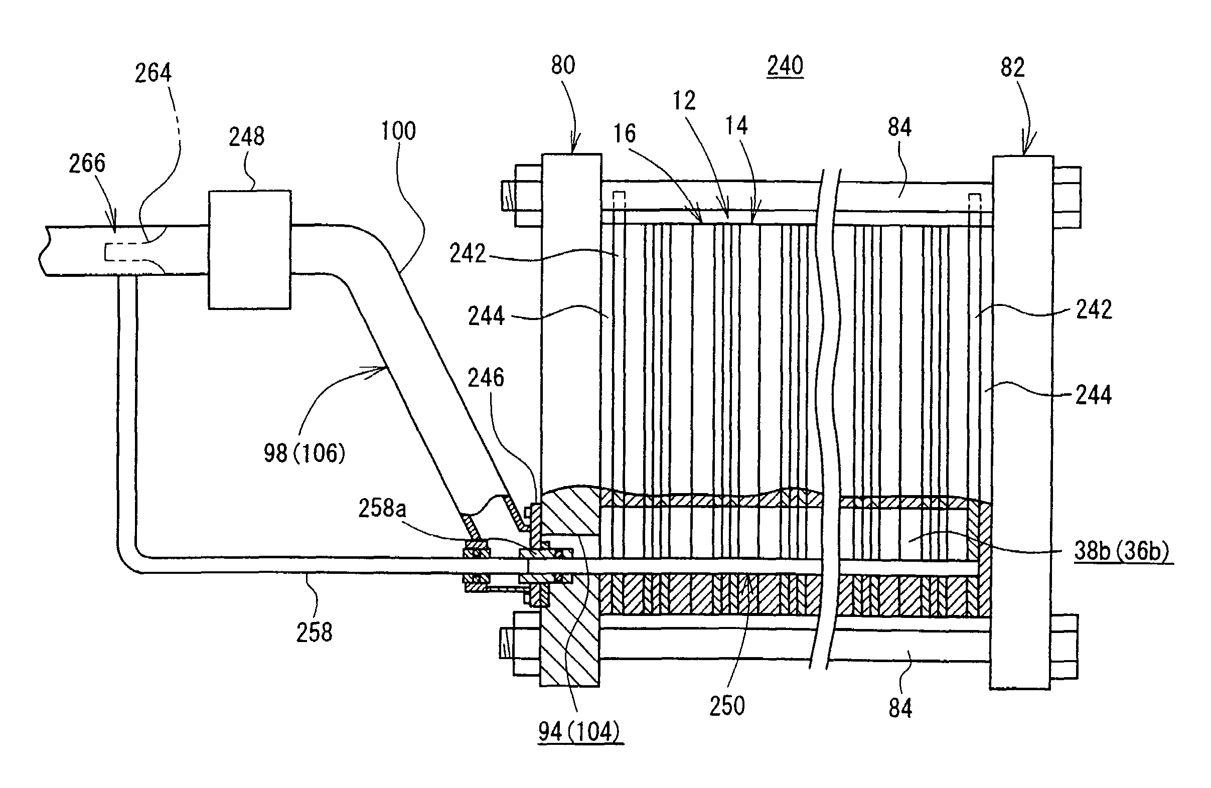
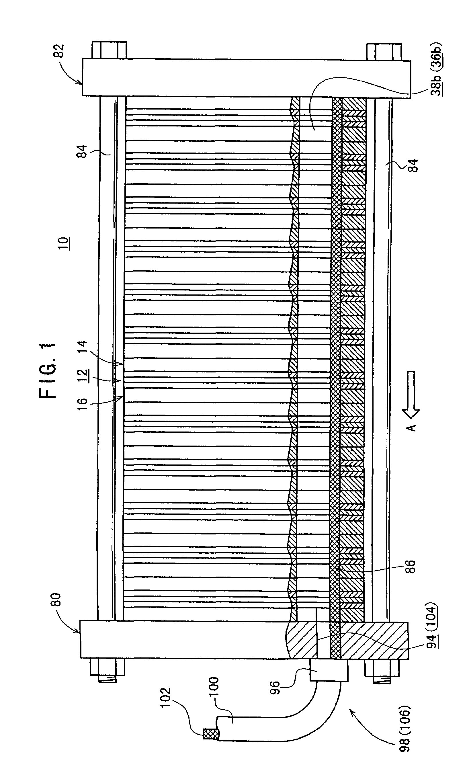
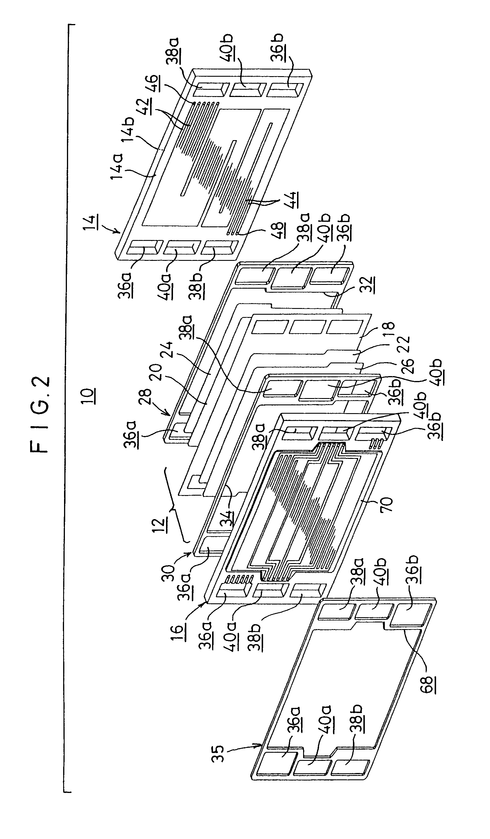
[0044]FIG. 1 shows a schematic longitudinal sectional view illustrating a fuel cell stack 10 according to the present invention, and FIG. 2 shows an exploded perspective view illustrating major components of the fuel cell stack 10 described above.

[0045]The fuel cell stack 10 comprises a fuel cell unit 12, and first and second separators 14, 16 for supporting the fuel cell unit 12 interposed therebetween. A plurality of sets of these components are stacked with each other. The fuel cell unit 12 includes a solid polymer ion exchange membrane 18, and a cathode electrode 20 and an anode electrode 22 which are arranged with the ion exchange membrane 18 intervening therebetween. First and second gas diffusion layers 24, 26, each of which is composed of, for example, porous carbon paper as a porous layer, are arranged for the cathode electrode 20 and the anode electrode 22.

[0046]First and second gaskets 28, 30 are provided on both sides of the fuel cell unit 12. The first gasket 28 has a l...

fifth embodiment

[0082]FIG. 13 shows a longitudinal sectional view illustrating a fuel cell stack 160 according to the present invention. In the fuel cell stack 160, porous water-absorbing tubes 162 are arranged for the outlet side oxygen-containing gas communication hole 38b and the outlet side fuel gas communication hole 36b. The porous water-absorbing tube 162 comprises a pipe member 164 and a plurality of wire members 166 arranged at the inside of the pipe member 164.

[0083]The pipe member 164 is provided with a plurality of holes 168 which are formed at portions to be arranged at the outlet side oxygen-containing gas communication hole 38b and the outlet side fuel gas communication hole 36b, making it possible to effect the permeation of water. On the other hand, no hole is provided at the portion exposed to the outside of the fuel cell stack 160. The pipe member 164 is constructed in an integrated manner. However, it is also preferable that a tube provided with the holes 168 and a tube having n...

sixth embodiment

[0084]FIG. 14 shows a vertical sectional view illustrating a porous water-absorbing tube 180 which constitutes a fuel cell stack according to the present invention. The porous water-absorbing tube 180 comprises a water-absorbing member 182 having a solid cross section which is embedded on the lower side in the direction of the gravity of each of the outlet side oxygen-containing gas communication hole 38b and the outlet side fuel gas communication hole 36b. The water-absorbing member 182 is composed of, for example, sponge. The upper surface of the water-absorbing member 182 is set at the position to provide a predetermined gap S from the second oxygen-containing gas connecting flow passage 48 and the second fuel gas connecting flow passage 66. It is possible to avoid any back flow of water.


PUM

PropertyMeasurementUnit
DC electric energyaaaaaaaaaa
power generationaaaaaaaaaa
hydrophilicaaaaaaaaaa

Abstract

A fuel cell stack is provided with an outlet side oxygen-containing gas communication hole. First and second oxygen-containing gas flow passage grooves are provided in the direction of the gravity while meandering in the horizontal direction on a surface of a first separator. The second oxygen-containing gas flow passage grooves communicate with the outlet side oxygen-containing gas communication hole via second oxygen-containing gas connecting flow passages. A porous water-absorbing tube, which is used to discharge water to the outside of the fuel cell stack in accordance with the capillary phenomenon and the difference in pressure of air, is provided for the outlet side oxygen-containing gas communication hole.

Description

BACKGROUND OF THE INVENTION[0001]1. Field of the Invention[0002]The present invention relates to a fuel cell stack which comprises a fuel cell unit composed of a solid polymer ion exchange membrane interposed between an anode electrode and a cathode electrode, and separators for supporting the fuel cell unit interposed therebetween, the fuel cell units and the separators being stacked in the horizontal direction. The fuel cell stack is especially appropriate to be carried on a vehicle.[0003]2. Description of the Related Art[0004]For example, the solid polymer type fuel cell comprises a fuel cell unit including an anode electrode and a cathode electrode disposed opposingly on both sides of an electrolyte composed of a polymer ion exchange membrane (cation exchange membrane) respectively, the fuel cell unit being interposed between separators. Usually, the solid polymer type fuel cell is used as a fuel cell stack obtained by stacking a predetermined number of the fuel cell units.[0005...

Claims


Application Information

Patent Timeline
Patent Type & Authority Patents(United States)
IPC IPC(8): H01M8/00H01M2/00H01M2/02H01M2/14H01M8/12H01M8/04H01M8/10H01M8/24
CPCH01M8/0247H01M8/04156H01M8/04291H01M8/0267H01M8/04029H01M8/04171H01M8/2415H01M2008/1095Y02E60/50H01M8/2483H01M8/241H01M8/2457H01M8/0263H01M8/0258H01M8/2484
Inventor KOMURA, TAKASHISUGITA, NARUTOSHIINAI, SHIGERU
Owner HONDA MOTOR CO LTD
Why Eureka
Try Eureka