
High throughput screen

a high throughput, screen technology, applied in the field of high throughput screens, can solve the problems of unsuitable rapid screening of test compounds, unsuitable development of novel compounds acting on them, and suffer the same limitations, so as to achieve high throughput, high resistance seals, and high throughput

Inactive Publication Date: 2005-08-30
SOPHION BIOSCI
View PDF27 Cites 51 Cited by
  • Summary
  • Abstract
  • Description
  • Claims
  • Application Information

AI Technical Summary

Benefits of technology

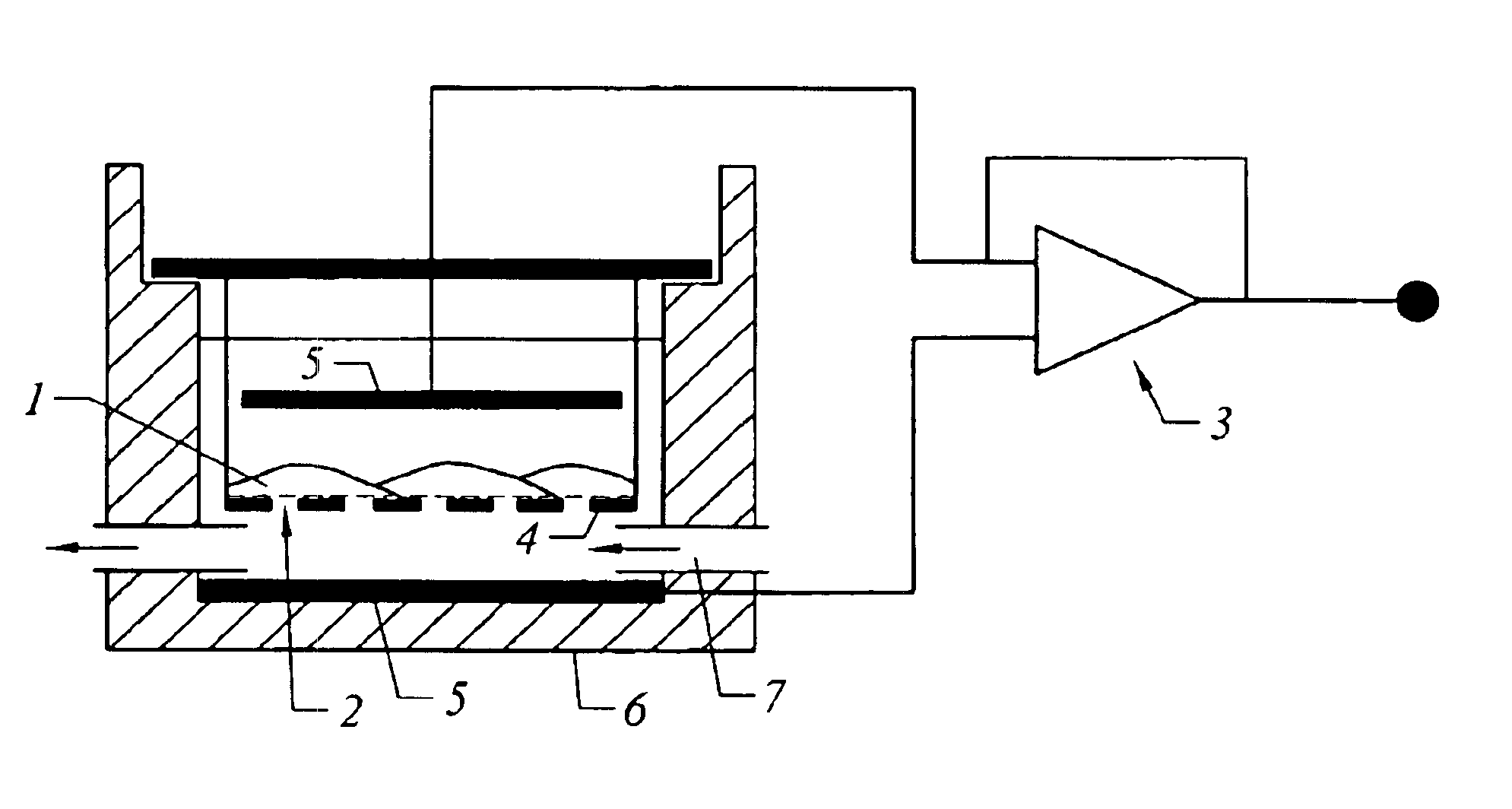
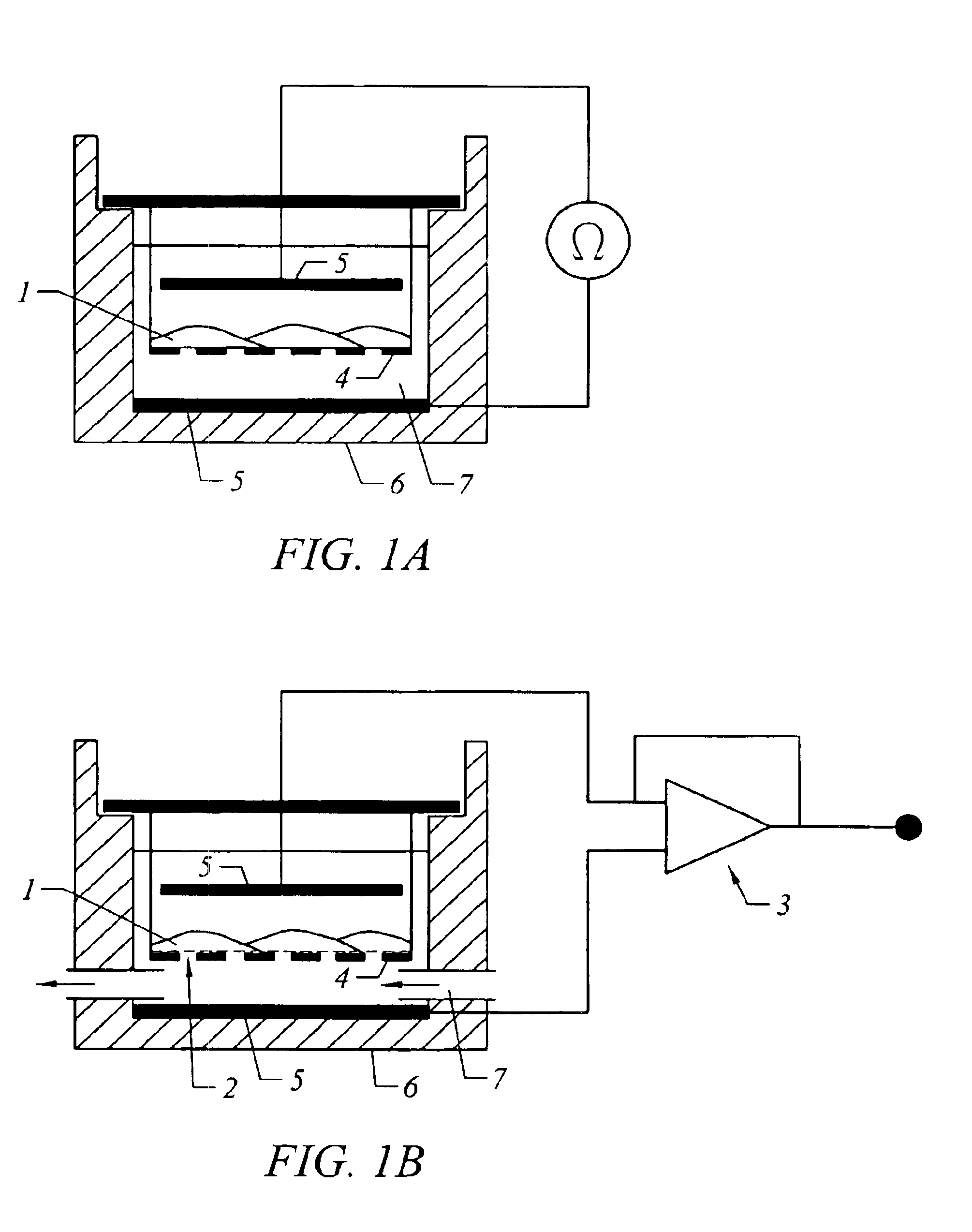
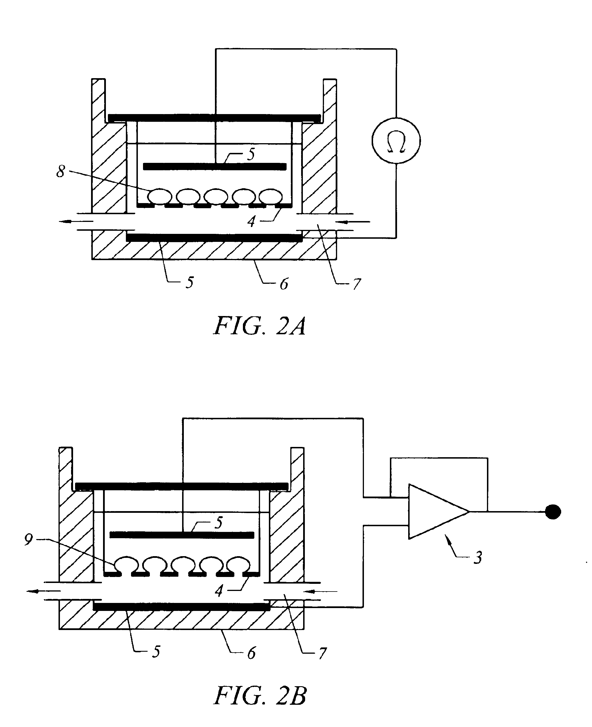
[0008]The present invention relates to a structure comprising a biological membrane and a porous or perforated substrate, a biological membrane, a substrate, a high throughput screen, methods for production of the structure membrane and substrate, and a method for screening a large number of test compounds in a short period. More particularly it relates to a structure comprising a biological membrane adhered to a porous or perforated substrate, a biological membrane capable of adhering with high resistance seals to a substrate such as perforated glass and the ability to form sheets having predominantly an ion channel or transporter of interest, a high throughput screen for determining the effect of test compounds on ion channel or transporter activity, methods for manufacture of the structure, membrane and substrate, and a method for monitoring ion channel or transporter activity in a membrane.

Problems solved by technology

Many drugs are known to exert their effect by modulation of ion channels, but the development of novel compounds acting on them is hampered considerably by the difficulty of screening at high-throughput rates for activity.
Conventional electrophysiological methods such as patch or voltage clamp techniques provide definitive mechanistic information but suffer from the problem that they are unsuited to the rapid screening of test compounds.
This apparatus suffers from the problems that it merely semi-automates the drug delivery system, not the patch clamp recording.
It therefore suffers from the same limitations as traditional patch-clamping with respect to speed of processing compounds and can in no way be considered a high-throughput system.

Method used


Image

  • High throughput screen
  • High throughput screen
  • High throughput screen

Examples


examples

[0079]An embodiment of the screen of the invention comprises a multi well plate with integrated recording devices, by which means a massively parallel voltage clamp (MPVC) can be performed on a plurality of wells in a plate within short periods of time (ca. 1-60 s). Preferably commercially available 96 or 384 well plates are employed, or the 96 or 384 position array format is adopted.

[0080]An embodiment of the screen of the invention preferably provides a throughput of test compounds in excess of 30,000 per week with bona fide electrophysiological ‘read-out’ of functional ion channel activity. An embodiment of the screen may provide high resolution both in terms of time; for a 96 well plate, 1 ms / point / voltage clamp setup. The sensitivity to modulation of channel activity is ≧1%.

[0081]An embodiment of the present invention provides a method which comprises the steps of measuring transepithelial electrical resistance across a contiguous layer of cells expressing predominantly an ion ...


PUM

PropertyMeasurementUnit
Diameteraaaaaaaaaa
Diameteraaaaaaaaaa
Diameteraaaaaaaaaa

Abstract

The present invention relates to a structure comprising a biological membrane and a porous or perforated substrate, a biological membrane, a substrate, a high throughput screen, methods for production of the structure membrane and substrate, and a method for screening a large number of test compounds in a short period. More particularly it relates to a structure comprising a biological membrane adhered to a porous or perforated substrate, a biological membrane capable of adhering with high resistance seals to a substrate such as perforated glass and the ability to form sheets having predominantly an ion channel or transporter of interest, a high throughput screen for determining the effect of test compounds on ion channel or transporter activity, methods for manufacture of the structure, membrane and substrate, and a method for monitoring ion channel or transporter activity in a membrane.

Description

FIELD OF THE INVENTION[0001]The present invention relates to a structure comprising a biological membrane and a porous or perforated substrate, a biological membrane, a substrate, a high throughput screen, methods for production of the structure membrane and substrate, and a method for screening a large number of test compounds in a short period. More particularly it relates to a structure comprising a biological membrane adhered to a porous or perforated substrate, a biological membrane capable of adhering with high resistance seals to a substrate such as perforated glass and the ability to form sheets having predominantly an ion channel or transporter of interest, a high throughput screen for determining the effect of test compounds on ion channel or transporter activity, methods for manufacture of the structure, membrane and substrate, and a method for monitoring ion channel or transporter activity in a membrane.BACKGROUND OF THE INVENTION[0002]Ion channels are transmembrane prot...

Claims


Application Information

Patent Timeline
IPC IPC(8): G01N33/543G01N33/68G01N37/00G01N33/50
CPCG01N33/5438G01N33/6872G01N33/502B01L3/5025G01N33/48728G01N27/28G01N2500/04B01L2300/16B01L2300/0893Y10T29/49826B01L2300/0829G01N2500/10B01L2300/0851
Inventor OWEN, DAVID GERAINTBYRNE, NICHOLAS GERARD
Owner SOPHION BIOSCI
Learn More