Electric machine having an integrally continuous stator winding and stator slot bridges

a stator winding and electric machine technology, applied in the direction of magnets, electric generator control, magnetic bodies, etc., can solve the problems of complex winding shapes and designs, time-consuming winding, and difficult control of repeatability

Inactive Publication Date: 2005-08-30
PRATT & WHITNEY CANADA CORP
View PDF54 Cites 935 Cited by
  • Summary
  • Abstract
  • Description
  • Claims
  • Application Information

AI Technical Summary

Benefits of technology

[0009]In another aspect, the invention provides a machine operable as an alternator, the machine comprising: a rotor having a plurality of magnetic poles; a first winding electrically connected to a machine output, the output adapted to deliver generated output electricity from the machine; a second winding including a current-limiting device; and a stator adjacent the rotor, the first and second windings disposed in the stator, the stator and rotor together defining a first magnetic circuit around a portion of the first winding, the stator defi...

Problems solved by technology

Winding is time consuming and difficult to control repeatability from one machine to the next in mass marketing.
While improvements in winding design therefore proliferate to address this problem, un...

Method used


Image

  • Electric machine having an integrally continuous stator winding and stator slot bridges
  • Electric machine having an integrally continuous stator winding and stator slot bridges
  • Electric machine having an integrally continuous stator winding and stator slot bridges

Examples


Embodiment Construction

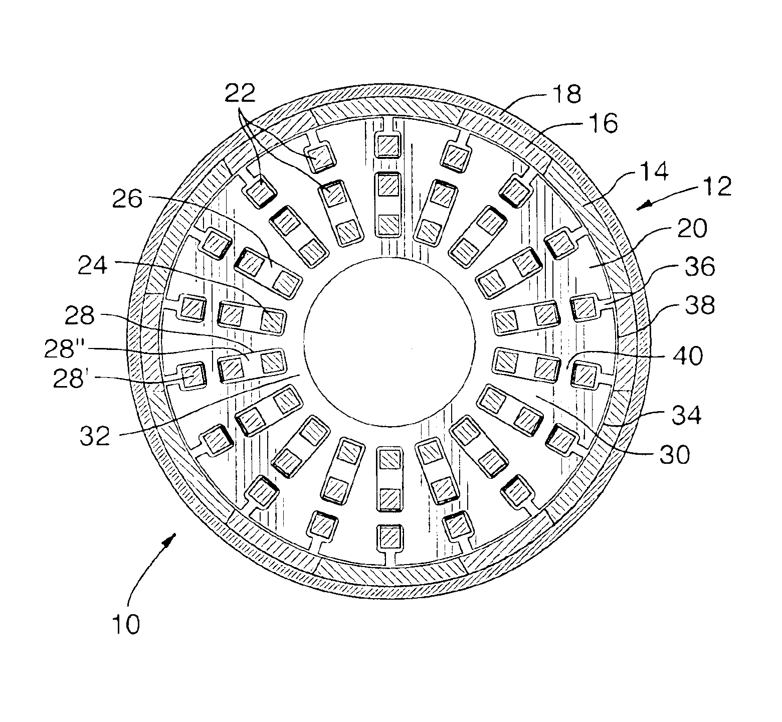
[0049]A permanent magnet (PM) machine according to the present invention is depicted in at 10 in FIGS. 4a to 4f. Referring first to FIGS. 4a and 4b, PM machine 10 has a rotor 12 which includes a plurality of permanent magnets 14 retained by a yoke 16 and retention sleeve portion 18. Machine 10 also has a stator 20 which includes at least a primary winding 22 and at least a secondary winding 24 (for clarity, only one of each such winding is shown), separated in this embodiment by a winding air gap 26 and disposed in radial slots 28 between a plurality of adjacent teeth 30 in a back iron 32. (For ease of illustration in FIG. 4b, the adjacent elements of secondary winding 24 are shown unconnected.) The winding air gap serves as insulation and may be replaced by other suitable insulation. A rotor air gap 34 separates rotor 12 and stator 20 in a typical fashion, and a stator tooth gap 36 separates adjacent teeth 30 at a rotor interface surface 38 of stator 20. Primary winding 22 and seco...


PUM

PropertyMeasurementUnit
Shapeaaaaaaaaaa

Abstract

The invention includes an electric machine having a rotor, stator and at least one winding in the stator adapted to conduct a current, and a secondary winding, electrically isolated from the first winding and inductively coupled to the first winding, which may be used to control at least one of the output voltage and current of the first winding.

Description

RELATED APPLICATION[0001]This application is a continuation application of U.S. Ser. No. 10 / 444,952 filed May 27, 2003, which application is hereby incorporated by reference.TECHNICAL FIELD[0002]The invention relates to electric machines such as alternators and motors and, more particularly, to a novel architecture for such machines.BACKGROUND OF THE ART[0003]Radial gap electric machines typically have stator windings which are in slots defined in the stator. The windings are provided in the stator directly by a winding machine, or pre-wound around a bobbin or mandrel and then transferred to the stator. Winding is time consuming and difficult to control repeatability from one machine to the next in mass marketing. While improvements in winding design therefore proliferate to address this problem, unfortunately most result in complex winding shapes and designs, and in multi-piece windings which still must be assembled, and which introduce new issues which challenge repeatability and ...

Claims


Application Information

Patent Timeline
IPC IPC(8): H02K3/16H02K3/12H02K7/18H02K21/12H02K21/22H02K21/14
CPCH02K1/2786H02K3/16H02K3/28H02K3/46H02K7/1823H02K11/048H02K16/04H02K21/046H02K21/22H02P9/02H02K3/12H02P2101/30H02K21/14Y10T29/49009Y10T29/49073H02K1/2791H02M7/00
Inventor BELL, JOSHUADOOLEY, KEVIN ALLAN
Owner PRATT & WHITNEY CANADA CORP
Why Eureka
Try Eureka