Low bias current/temperature compensation current mirror for linear power amplifier

a technology of bias current and temperature compensation, applied in the direction of amplifiers, amplifiers with semiconductor devices only, amplifiers with semiconductor devices, etc., can solve the problems of continuous current drain, output signal, and the least efficient of all the amplifier classes,

Inactive Publication Date: 2005-08-30
SKYWORKS SOLUTIONS INC
View PDF25 Cites 85 Cited by
  • Summary
  • Abstract
  • Description
  • Claims
  • Application Information

AI Technical Summary

Problems solved by technology

It is however the least efficient of all the classes of amplifiers, in as much that in ideal cases the power delivered to the load is typically only 50% of the D.C. power used.
The drawbacks of Class AB power amplifiers include the generation of an output signal which is not an exact linear reproduction of the input waveform, lower gain than that of a Class A type, continuous current drain, and lower efficiency compared to other amplifier types.
The drawbacks of a Class B amplifier include even higher distortion and lower gain compared to Class A and AB amplifiers.
This results in a signal with a non-constant envelope, requiring a transmitter having a minimal amount of both amplitude and phase distortion.
And although it exhibits better efficiency at low drive levels than a Class A type amplifier, the optimum low drive efficiency is limited by the linearity requirement under higher drive.
In general, as power efficiency improves under high drive, linearity will suffer.
In practice, balancing linearity and efficiency across all drive conditions is difficult.

Method used


Image

  • Low bias current/temperature compensation current mirror for linear power amplifier
  • Low bias current/temperature compensation current mirror for linear power amplifier
  • Low bias current/temperature compensation current mirror for linear power amplifier

Examples


Embodiment Construction

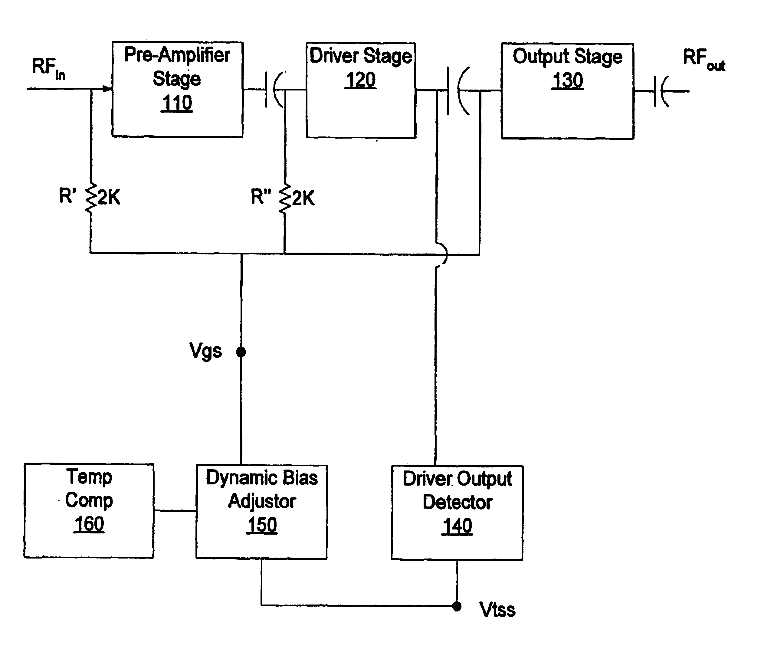
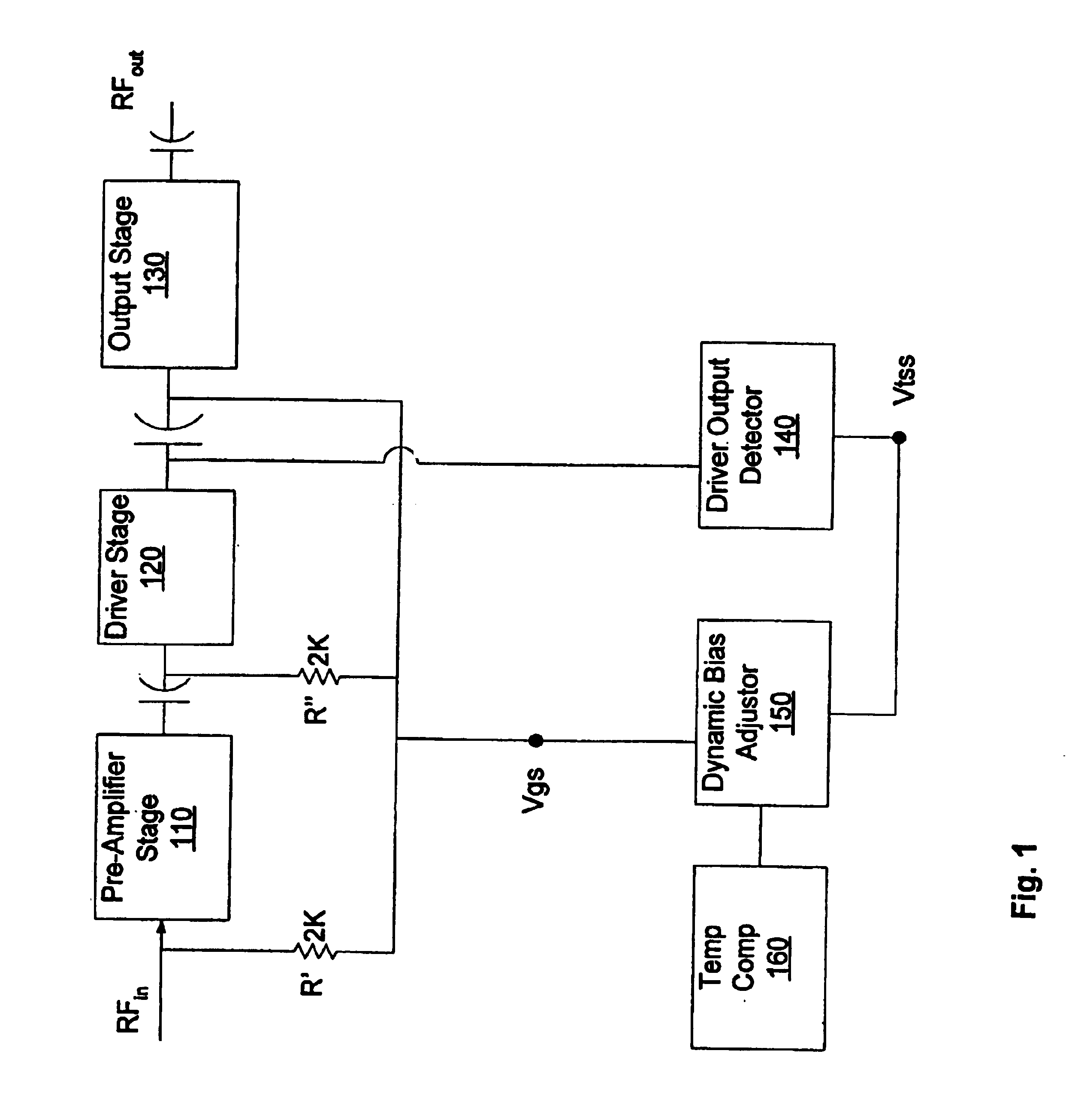
[0020]FIG. 1 illustrates a linear power amplifier including the novel dynamic bias features of the present invention. The amplifier includes a pre-amplifier stage 110, a driver amplifier stage 120, and an output amplifier stage 130. In a preferred embodiment, the output of the driver amplifier stage 120 is coupled to a driver output detector 140. A bias adjustor circuit 150 in accordance with the present invention is coupled to the driver ouptut detector 140. Additionally, the output of the bias adjustor circuit 150 is coupled to the three-stage amplifier circuit via a coupling circuit comprising resistors R′ and R″. Preferably resistors R′ and R″ are each 2KΩ. Temperature compensation circuit 160 is coupled to the bias adjustor circuit 150.

[0021]Each of the three stages 110, 120, 130 is preferably comprised of a depletion mode Gallium Arsenide (GaAs) Field Effect Transistor (FET) gain amplifier. In general, the depletion mode FET current characteristics are such that it draws maxim...


PUM


Abstract

A power amplifier circuit whose performance is optimized by operating its stages in substantially close to a Class B mode by reducing quiescent current during low driver signal levels. As the driver signal amplitude increases, the operation of the amplifier is configured to dynamically adjust to be in a Class AB mode, thereby increasing the power efficiency of the overall circuit at kiw drive levels. A further enhancement to the power amplifier circuit includes a temperature compensation circuit to adjust the bias of the amplifier so as to stabilize the performance in a wide temperature range.

Description

CROSS REFERENCE TO RELATED APPLICATIONS[0001]This is a continuation of application Ser. No. 09 / 634,628, filed Aug. 8, 2000, that claims the benefit of U.S. Provisional Application No. 60 / 148,099, filed Aug. 10, 1999.FIELD OF THE INVENTION[0002]This invention relates to amplifier circuitry and, more particularly, to a low bias current and temperature compensation current mirror for use in a linear power amplifier.BACKGROUND OF THE INVENTION[0003]Power amplifiers are categorized into several classes of operation. Some of these classes include Class-A, Class-B and Class-AB. A Class A power amplifier is defined as an amplifier with or without negative feedback, and in its ideal case is characterized with the greatest fidelity in faithfully amplifying an input signal with the least distortion. It conducts output current throughout 100% of the input signal waveform. In other words it exhibits a conduction angle of exactly 2π radians. In most cases it exhibits the greatest gain of all powe...

Claims


Application Information

Patent Timeline
Patent Type & Authority Patents(United States)
IPC IPC(8): H03F1/02H03F1/30
CPCH03F1/0272H03F1/301H03F2200/18H03F2200/504H03F2200/99
Inventor LOPEZ, OSVALDO JORGEBAYRUNS, ROBERTSINGH, MAHENDRA
Owner SKYWORKS SOLUTIONS INC
Why Eureka
Try Eureka