
Serializer and method of serializing parallel data into serial data stream

a serial data stream and serializer technology, applied in parallel/series conversion, electrical equipment, code conversion, etc., can solve the problems of serializer consuming a lot of power and may again induce jitter, and achieve the effect of low power condition, less jitter and high speed

Inactive Publication Date: 2005-08-30
SAMSUNG ELECTRONICS CO LTD
View PDF6 Cites 15 Cited by
  • Summary
  • Abstract
  • Description
  • Claims
  • Application Information

AI Technical Summary

Benefits of technology

The present invention provides a serializer that removes the coupling effect and reduces jitter due to inter symbol interference (ISI) in a serial data stream. The serializer includes a logic section and an inverter for each data stage, and each stage includes an AND gate and a PMOS and NMOS transistor pair. The logic section receives the data and the clock signals and performs the logical AND operation to output the data. The inverter then inverts the data and outputs it as the serial data stream. The serializer also includes a first and second logic section for separately processing first and second data, and a first and second inverter for separately outputting the first and second data. The technical effect of the invention is to improve the quality of the serial data stream and reduce the impact of ISI on the data transmission.

Problems solved by technology

In yet another conventional serializer, when data and clock signals are input to the serializer, the voltage output at floating nodes of serially connected NMOS transistors affects an output signal of the serializer, and jitter may again be induced.
In addition, a load of PMOS transistor is turned on always even during power down status and the serializer consumes a lot of power.

Method used


Image

  • Serializer and method of serializing parallel data into serial data stream
  • Serializer and method of serializing parallel data into serial data stream
  • Serializer and method of serializing parallel data into serial data stream

Examples


Embodiment Construction

[0050]Detailed, illustrative, exemplary embodiments of the present invention are disclosed herein. However, specific structural and functional details disclosed herein are merely representative for purposes of describing exemplary embodiments of the present invention.

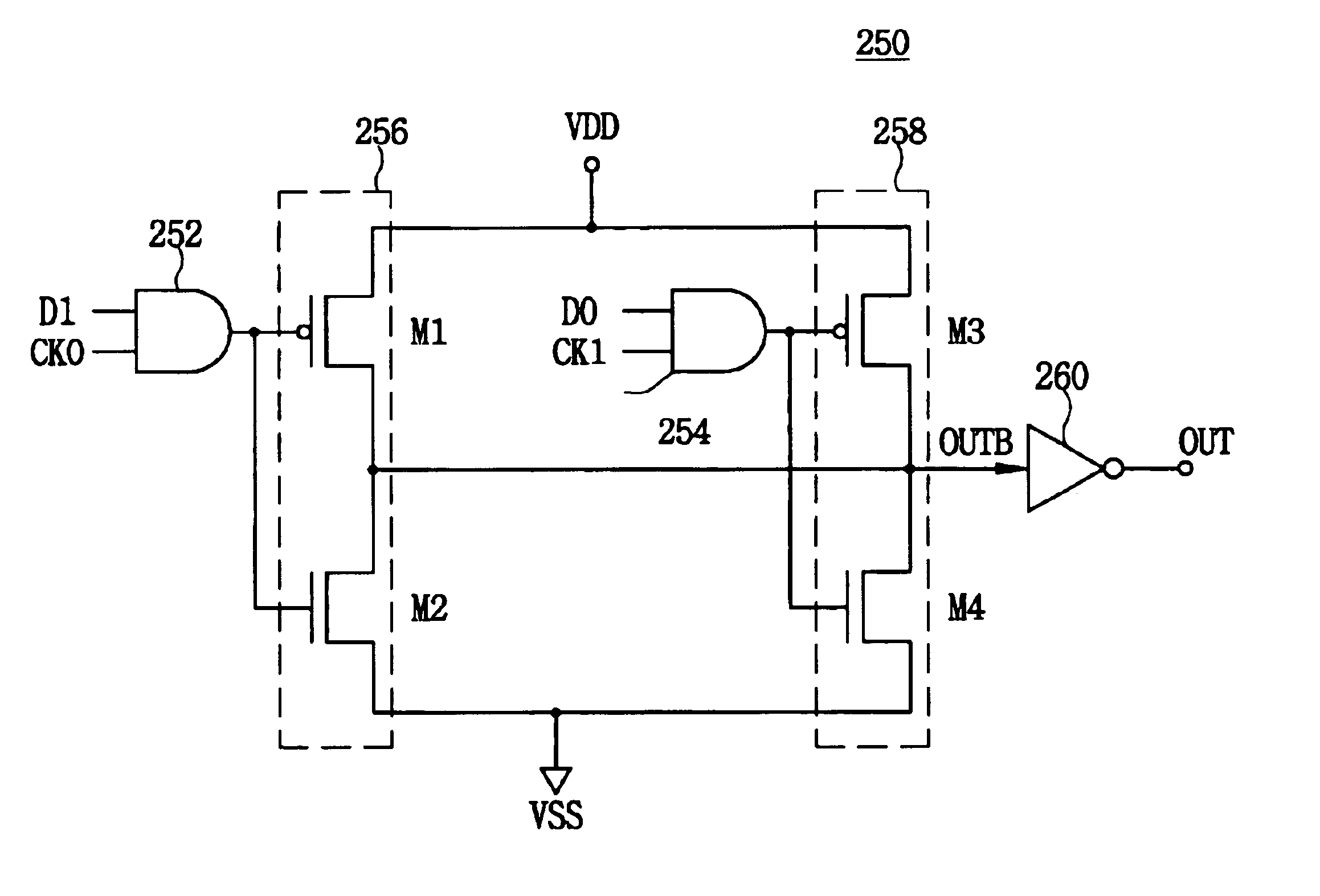
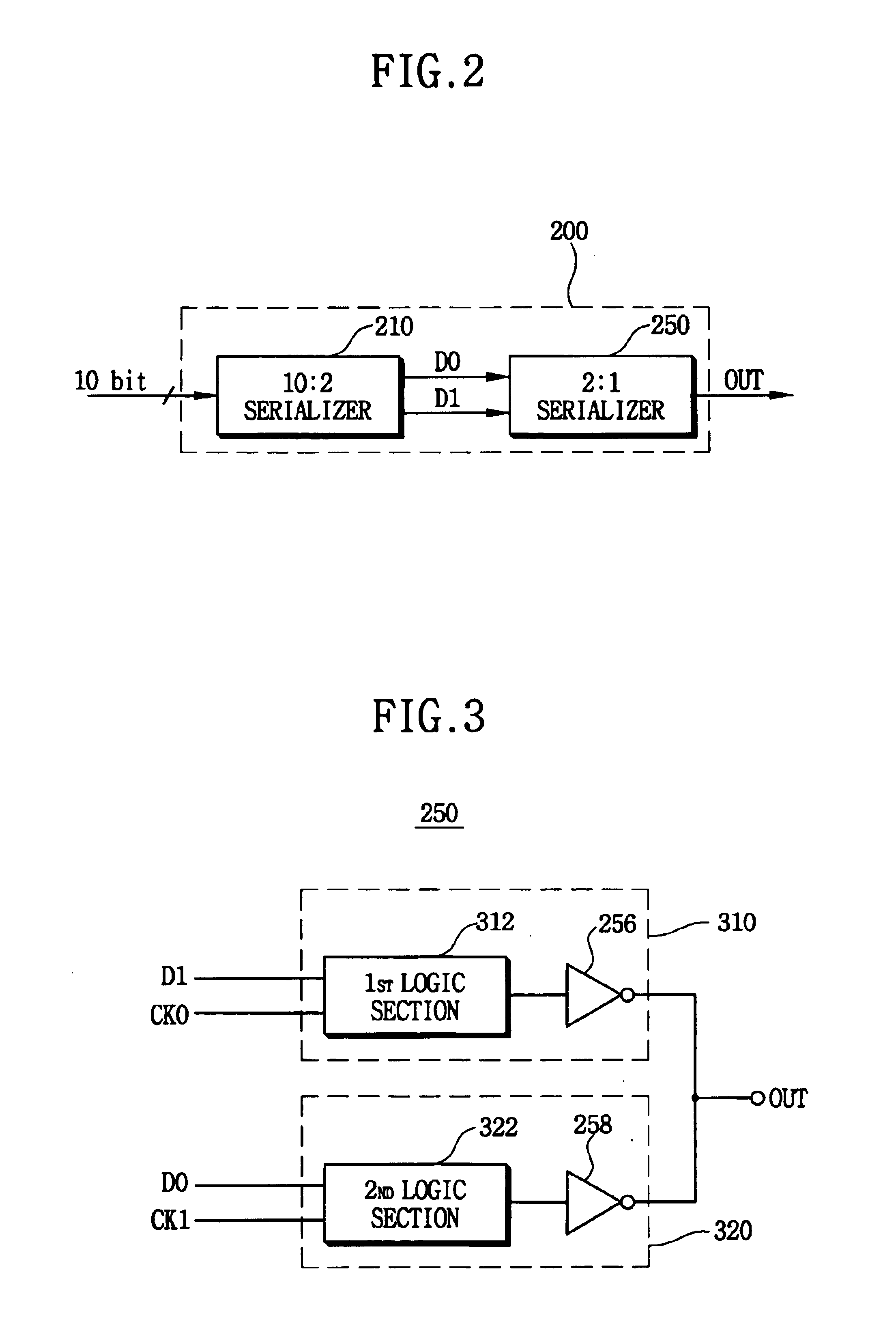
[0051]FIG. 2 is a block diagram showing a 10:1 serializer having a 2:1 serializer according to an exemplary embodiment of the present invention. The 10:1 serializer 200 may be implemented as a 10:2 serializer 210 and a 2:1 serializer 250 or a 10:5 serializer and a 5:1 serializer depending on a clock speed.

[0052]Referring to FIG. 2, the 10:1 serializer 200 includes the 10:2 serializer 210 and the 2:1 serializer 250. The 10:2 serializer 210 receives 10 bits of data in parallel and outputs two data signals D0 and D1. The 2:1 serializer250 receives the two data signals D0 and D1 and serializes the two data signals D0 and D1 to output a serialized data stream via an output terminal OUT.

[0053]FIG. 3 is a block diagram showing...


PUM


Abstract

A serializer serializes N data (N>2) in N stages into a serial data stream. Each stage includes a logic section and a first inverter. The logic section receives i-th data (where i is less than or equal to N) of the N parallel data to output the i-th data or inverted i-th data in response to an active status or an inactive status of an j-th clock signal (where j is less than or equal to N) of the N clock signals. The first inverter receives the i-th data or the inverted i-th data from the logic section and inverts the i-th data or the inverted i-th data to output a first output signal. The output signal of the serializer may have reduced jitter even when the serializer operates in a high speed and a low power condition.

Description

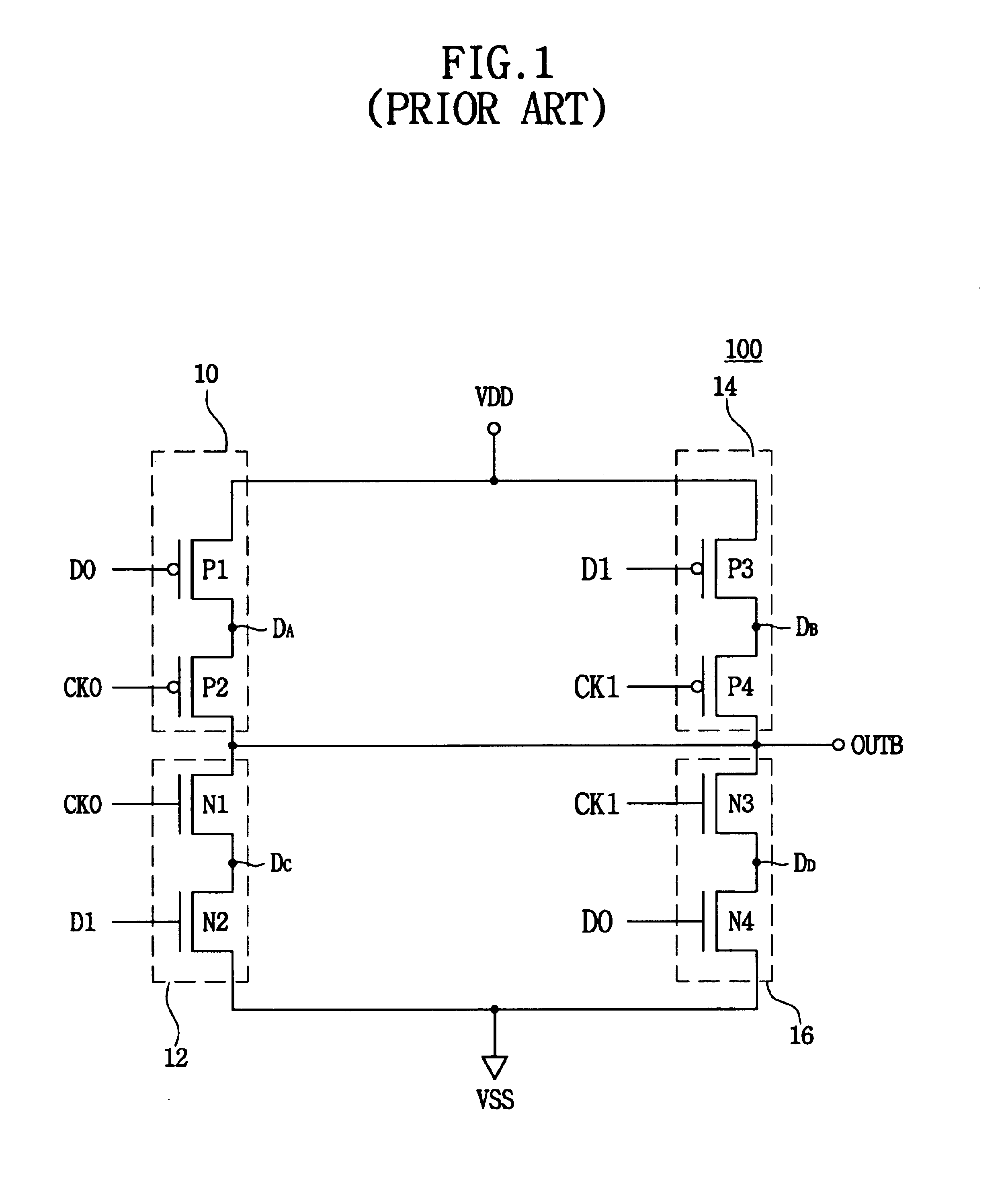
CROSS-REFERENCE TO RELATED APPLICATIONS[0001]This application relies for priority upon Korean Patent Application No. 2003-52380 filed on Jul. 29, 2003, the contents of which are herein incorporated by reference in its entirety.BACKGROUND OF THE INVENTION[0002]1. Field of the Invention[0003]The present invention relates to a serializer and a method of serializing parallel data into a serial data stream, and more particularly to a serializer and a method of serializing parallel data into a serial data stream, which reduces or prevents the jitter of a serialized output signal in high speed and / or low voltage applications.[0004]2. Description of the Related Art[0005]FIG. 1 is a circuit diagram showing a conventional 2:1 serializer 100. The conventional 2:1 serializer 100 includes a first pull-up section 10, a second pull-up section 14, a first pull-down section 12 and a second pull-down section 16. The first pull-up section 10 includes two PMOS transistors P1 and P2, the second pull-up ...

Claims


Application Information

Patent Timeline
Patent Type & Authority Patents(United States)
IPC IPC(8): H03M9/00
CPCH03M9/00
Inventor KIM, CHI-WON
Owner SAMSUNG ELECTRONICS CO LTD
Learn More