Millimeter wave radar

a radar and millimeter wave technology, applied in wave based measurement systems, instruments, reradiation, etc., can solve the problems of increasing weight, complex structure and production process of antenna units, and unnecessary bodies would be detected, etc., to achieve excellent weathering performance, excellent detection performance, and light weight

Inactive Publication Date: 2005-08-30
HITACHI LTD
View PDF11 Cites 43 Cited by
  • Summary
  • Abstract
  • Description
  • Claims
  • Application Information

AI Technical Summary

Benefits of technology

[0004]In view of the above, it is an object of the present invention to provide a millimeter wave radar which is light in weight, excellent in weathering performance, inexpensive, and excellent in detection performance.

Problems solved by technology

On the other hand, the millimeter wave radar has the problem that the side lobe of the transmitted electromagnetic wave is reflected by surrounding bodies, with the result that unnecessary bodies would also be detected.
However, according to the technique described in Japanese Patent Laid-open No. 10-126146, since the metallic plate or absorber mounted to the periphery of the transmission-reception antenna is separate from the radome, the structure and production process of the antenna unit become complicated.
In addition, the metallic plate or absorber itself must have a certain degree of strength, so that the metallic plate or absorber itself must be thick to a certain extent, resulting in the problem of an increase in weight.
Furthermore, since the metallic plate or absorber is exposed to rain and winds, it has still the problem in weathering performance.

Method used


Image

  • Millimeter wave radar
  • Millimeter wave radar
  • Millimeter wave radar

Examples


embodiment 1

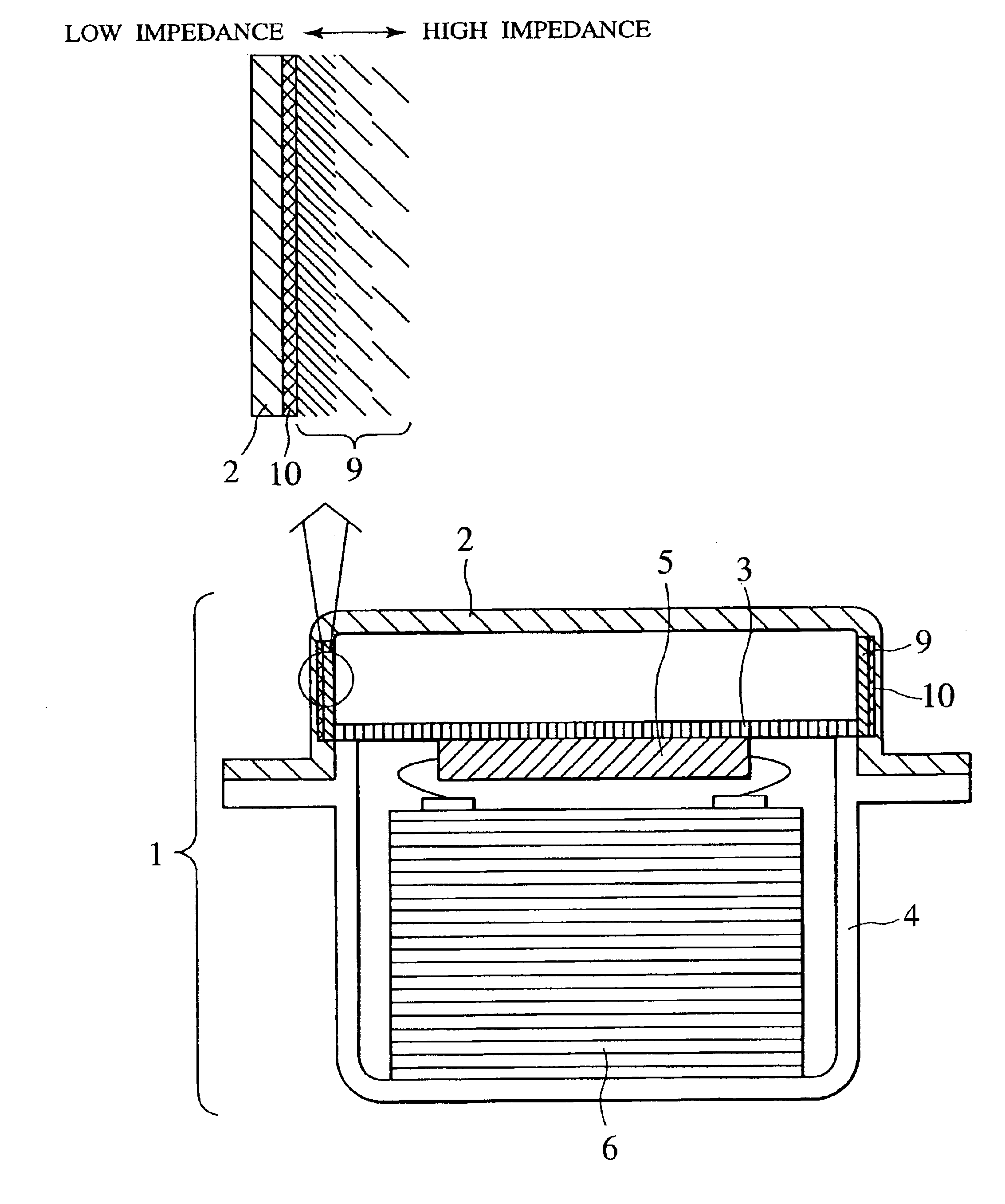
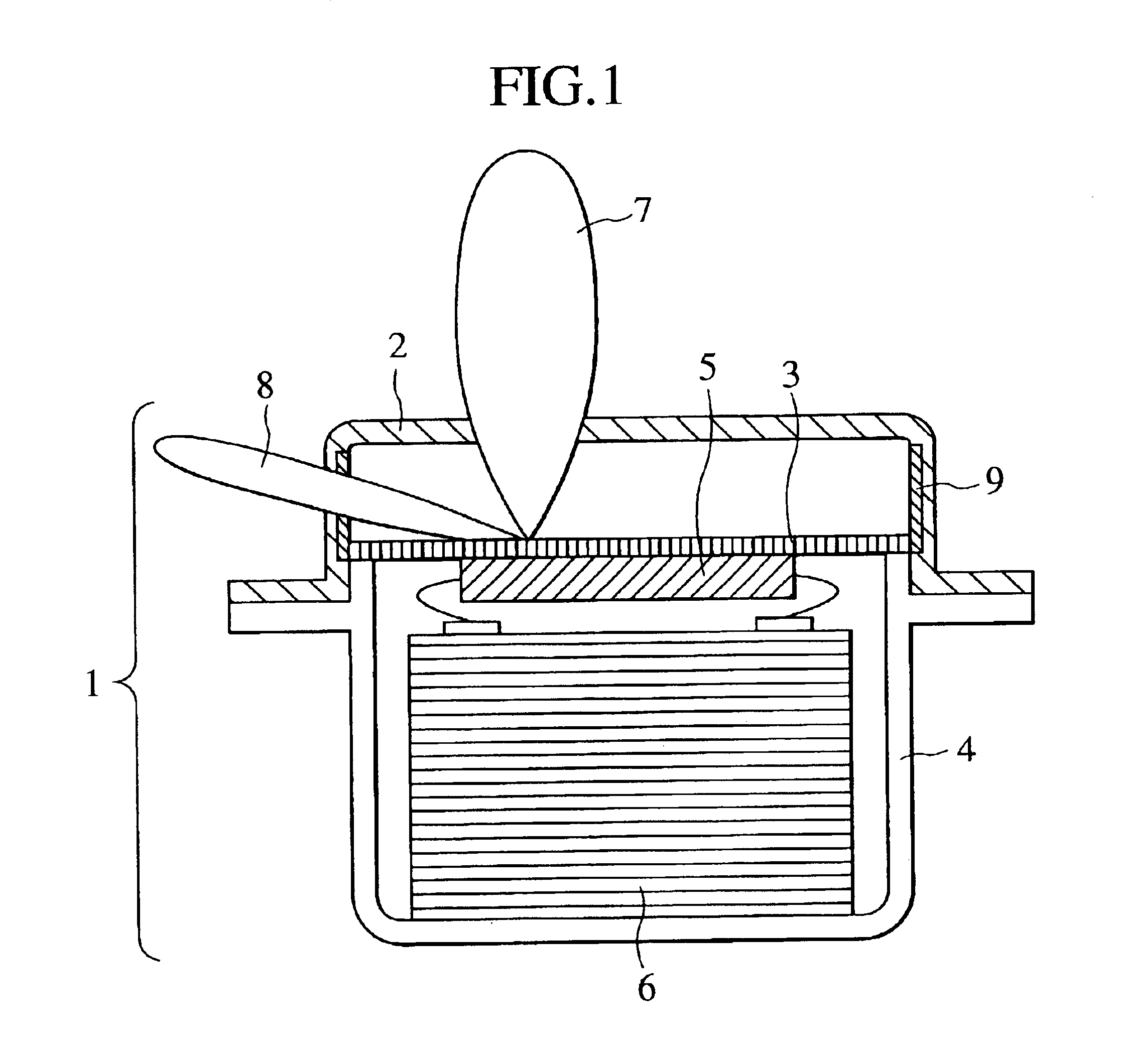
[0017]FIG. 1 is a cross-sectional view of a millimeter wave radar. The millimeter wave radar shown in FIG. 1 includes a radome 2, an antenna base 3 in which a transmission-reception antenna is mounted, a control circuit 6, an RF module 5, and a housing 4 for fixing the antenna base 3 and accomodating the control circuit 6 and the RF module therein. Reference numeral 7 in FIG. 1 shows a main beam of the transmitted electromagnetic wave transmitted from the transmission-reception antenna, and reference numeral 8 shows a side lobe of the transmitted electromagnetic wave transmitted from the transmission-reception antenna, in the form of conceptual illustration for easier understanding. The transmission-reception antenna herein means an antenna arrangement so constituted as to be capable of transmission and reception, and the case where a transmission antenna and a reception antenna are separately arranged should be also included in the meaning of the term “transmission-reception antenn...

embodiment 2

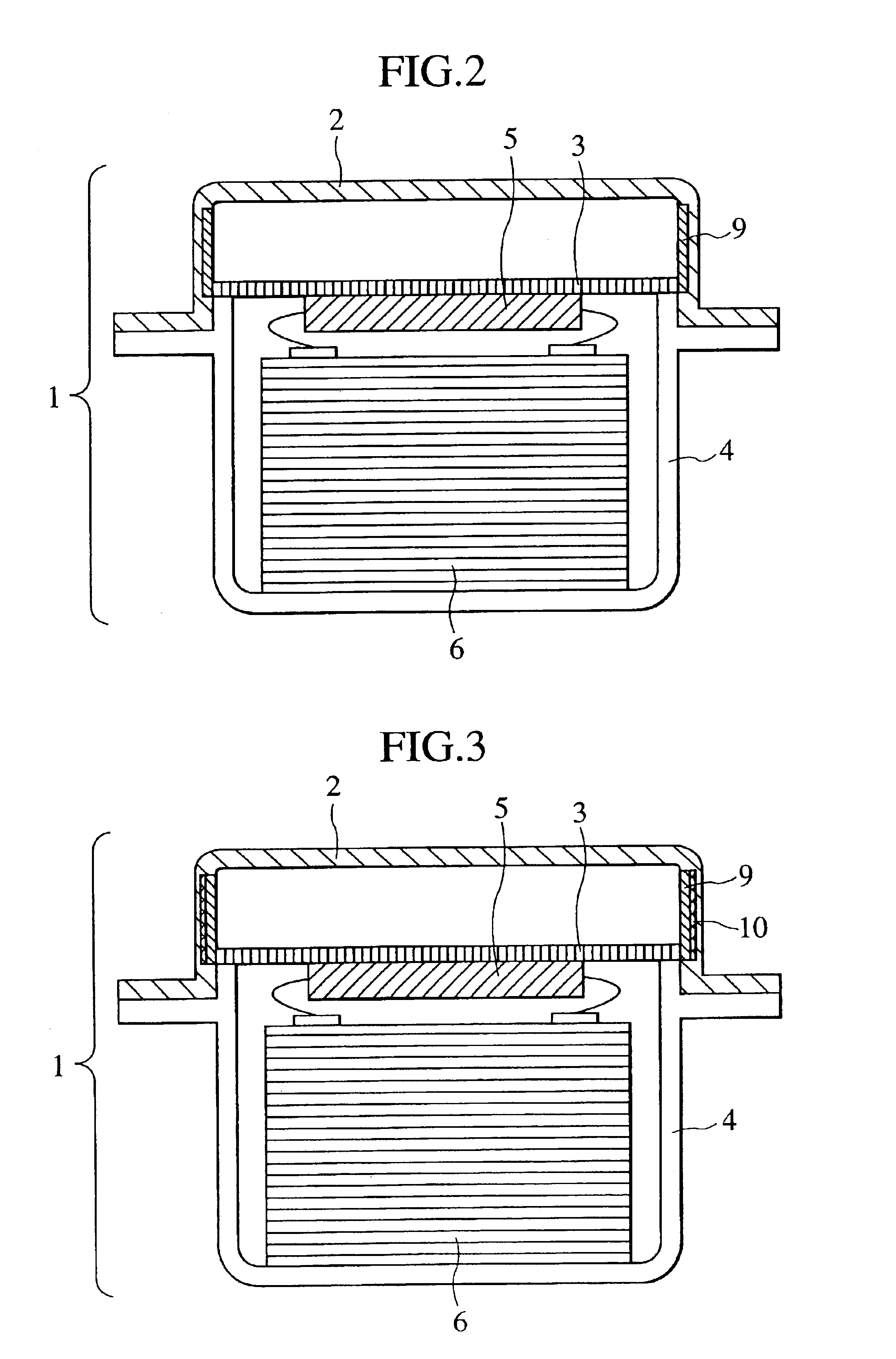
[0023]A cross-sectional view of a millimeter wave radar according to the present embodiment is shown in FIG. 3. The difference between the millimeter wave radar according to the present embodiment and the millimeter wave radar according to Embodiment 1 lies in that a layer having a dielectric loss higher than that of the radome or a magnetic loss layer 9 is disposed as a side lobe absorbing means and, further, a conductor layer 10 is disposed on the outside of thereof. With such a constitution, the permeating wave to the outside of the radome can be completely removed while restraining the reflection of the transmitted electromagnetic wave on the inside surface of the radome. Such a constitution is a constitution of a matching type electromagnetic wave absorber backed with a reflector. Absorption mechanisms include a multiple reflection effect by critical coupling between the surface reflection wave and the multiple reflection waves in the electromagnetic wave absorber, and an atten...

embodiment 3

[0027]A cross-sectional view of a millimeter wave radar according to the present embodiment is shown in FIG. 4. The present embodiment resides in that the impedance to the transmitted electromagnetic wave of a layer higher in dielectric loss than the radome or a magnetic loss layer 9 is gradually reduced, from the side of the layer higher in dielectric loss than the radome or the magnetic loss layer 9 toward a conductor layer 10 (from the inside to the outside of the radome). To be more specific, the layer higher in dielectric loss than the radome or the magnetic loss layer 9 is composed of a multiplicity of layers differing in the impedance. With this constitution, it is possible to enhance the electromagnetic wave absorption characteristic for the electromagnetic wave transmitted from the transmission-reception antenna and obliquely incident on the inside surface of the radome (oblique incident wave).

[0028]In this case, if the outermost layer, on the conductor layer side, of the l...


PUM


Abstract

A millimeter wave radar for the purpose of automatic operation or collision prevention of a vehicle which solves the problem that a side lobe of a transmitted electromagnetic wave is reflected by surrounding bodies and the reflected wave is received, with the result that unnecessary bodies may also be detected. A layer higher in dielectric loss than a radome or a magnetic loss layer and a conductor layer in a mesh form are embedded in a part of the inside surface of the radome, whereby it is possible to provide a millimeter wave radar which is light in weight, excellent in weathering performance, inexpensive, and excellent in detection performance.

Description

BACKGROUND OF THE INVENTION[0001]The present invention relates to a millimeter wave radar mounted on a vehicle.[0002]A millimeter wave radar is used for the purpose of automatic operation or collision prevention of a vehicle. The millimeter wave radar is a system for transmitting a millimeter electromagnetic wave in a desired direction, receiving the reflection of the transmitted wave, and preliminarily detecting a body which may act as an obstacle. On the other hand, the millimeter wave radar has the problem that the side lobe of the transmitted electromagnetic wave is reflected by surrounding bodies, with the result that unnecessary bodies would also be detected. As a countermeasure against this problem, a technique of mounting a metallic plate or an absorber to the periphery of the transmission-reception antenna surface in the antenna unit in the state of projecting from the surface of the transmission-reception antenna so as thereby to reduce the side lob has been described, for...

Claims


Application Information

Patent Timeline
Patent Type & Authority Patents(United States)
IPC IPC(8): G01S7/03H01Q17/00H01Q1/42G01S13/93H01Q1/52
CPCG01S7/03G01S7/032H01Q1/42H01Q1/421H01Q17/001Y10S977/95
Inventor FUJIEDA, TADASHIKURODA, HIROSHINAKAZAWA, TERUMISUZUKI, MITSUSHIGE
Owner HITACHI LTD
Why Eureka
Try Eureka